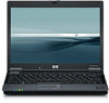
Compaq 2510p HP Compaq 2510p Notebook PC - Maintenance and Service Guide
Compaq 2510p - Notebook PC Manual
 |
View all Compaq 2510p manuals
Add to My Manuals
Save this manual to your list of manuals |
Compaq 2510p manual content summary:
- Compaq 2510p | HP Compaq 2510p Notebook PC - Maintenance and Service Guide - Page 1
HP Compaq 2510p Notebook PC Maintenance and Service Guide - Compaq 2510p | HP Compaq 2510p Notebook PC - Maintenance and Service Guide - Page 2
Inc. Microsoft, Windows, and Windows Vista are either services. Nothing herein should be construed as constituting an additional warranty. HP shall not be liable for technical or editorial errors or omissions contained herein. First Edition: June 2007 Third Edition: July 2008 Document Part - Compaq 2510p | HP Compaq 2510p Notebook PC - Maintenance and Service Guide - Page 3
MSG revision history Revision A Publication date October 2009 Description The fingerprint reader board cable is included in the Cable Kit, spare part number 451722-001. The information was updated in the following locations: Illustrated parts catalog on page 18, Cable Kit on page 26, Sequential - Compaq 2510p | HP Compaq 2510p Notebook PC - Maintenance and Service Guide - Page 4
iv MSG revision history - Compaq 2510p | HP Compaq 2510p Notebook PC - Maintenance and Service Guide - Page 5
overheating the computer, do not place the computer directly on your lap or obstruct the computer air vents. Use the computer only on a hard, flat surface. Do not allow another hard and the AC adapter comply with the user-accessible surface temperature limits defined by the International Standard for - Compaq 2510p | HP Compaq 2510p Notebook PC - Maintenance and Service Guide - Page 6
vi Safety warning notice - Compaq 2510p | HP Compaq 2510p Notebook PC - Maintenance and Service Guide - Page 7
...26 Mass storage devices ...27 Miscellaneous parts ...27 Sequential part number listing ...29 4 Removal and replacement procedures Preliminary replacement requirements 34 Tools required ...34 Service considerations ...34 Plastic parts ...34 Cables and connectors 35 Drive handling 35 Grounding - Compaq 2510p | HP Compaq 2510p Notebook PC - Maintenance and Service Guide - Page 8
Workstation guidelines 37 Equipment guidelines 38 Unknown user password 39 Component replacement procedures 40 Serial number ...40 Computer feet ...40 Battery ...41 SIM ...42 Bluetooth module ...43 Memory module ...45 RTC battery ...47 WLAN module ...48 Hard drive ...52 WWAN module ...54 Optical - Compaq 2510p | HP Compaq 2510p Notebook PC - Maintenance and Service Guide - Page 9
117 Performing a recovery ...117 Performing a recovery from the recovery discs 118 Performing a recovery from the hard drive 118 Initiating a recovery in Windows 119 Initiating a recovery from the hard drive recovery partition 119 Backup and recovery using Windows XP 120 Creating recovery discs - Compaq 2510p | HP Compaq 2510p Notebook PC - Maintenance and Service Guide - Page 10
a recovery in Windows 125 Initiating a recovery from the hard drive recovery partition 125 9 Connector pin assignments Audio-out (headphone) ...126 Audio-in (microphone) ...126 External monitor ...127 RJ-11 (modem) ...128 RJ-45 (network) ...128 Universal Serial Bus ...129 10 Power cord set - Compaq 2510p | HP Compaq 2510p Notebook PC - Maintenance and Service Guide - Page 11
1 Product description Category Branding Processors Chipsets Graphics Panels Memory Hard drives Description ● Long name: HP Compaq 2510p Notebook PC ● Short name: HP Compaq 2510p ● Logo badge: Compaq 2510p Intel® Core™ Duo processors: ● U7600 1.20-GHz processor with 533-MHz Front Side Bus (FSB) and - Compaq 2510p | HP Compaq 2510p Notebook PC - Maintenance and Service Guide - Page 12
ATA ● Removable with two screws ● Supports the following optical formats: ◦ DVD±RW and CD-RW Super Multi Double-Layer Combo Drive ◦ DVD/CD-RW Combo Drive ◦ DVD-ROM Drive ● Supports no-optical-drive option with blank bezel Supports an external Universal Serial Bus (USB) diskette drive only ● Azalia - Compaq 2510p | HP Compaq 2510p Notebook PC - Maintenance and Service Guide - Page 13
option ● One Type I/II PC Card slot ● 16-bit PCMCIA and 32-bit CardBus ● Integrated SD flash media slot (SD/MMC support) ● 1394a port ● Docking connector ● Headphone connector ● Microphone connector ● Primary battery connector ● RJ-11 modem port ● RJ-45 Ethernet port ● Smart AC adapter connector - Compaq 2510p | HP Compaq 2510p Notebook PC - Maintenance and Service Guide - Page 14
system Serviceability Description Preinstalled: ● Windows Vista Home Basic (32-bit) ● Windows Vista Business (32- and 64-bit) ● Windows® XP Professional ● FreeDOS Certified: Linux End-user replaceable parts: ● AC adapter ● Battery ● Bluetooth module ● Hard drive ● Memory module ● Optical drive - Compaq 2510p | HP Compaq 2510p Notebook PC - Maintenance and Service Guide - Page 15
2 External component identification Display components Item (1) (2) Component Display release latch Internal display switch (3) Internal microphone (4) Ambient light sensor Function Opens the computer. Turns off the display if the display is closed while the computer is on. Records sound. - Compaq 2510p | HP Compaq 2510p Notebook PC - Maintenance and Service Guide - Page 16
and fingerprint reader Item (1) Component Power button Windows Vista, select Start > Control Panel > System and Maintenance > Power Options. ● In Windows XP, select Start > Control Panel > Performance and Maintenance > Power Options. Launches Info Center, which enables you to open various software - Compaq 2510p | HP Compaq 2510p Notebook PC - Maintenance and Service Guide - Page 17
only) Volume scroll zone (8) HP Fingerprint Sensor Function Mutes and restores speaker sound. Adjusts speaker volume. Slide your finger to the left to decrease volume and to the right to increase volume. Allows a fingerprint logon to Windows, instead of a password logon. Keys NOTE: Your computer - Compaq 2510p | HP Compaq 2510p Notebook PC - Maintenance and Service Guide - Page 18
. If the computer is not plugged into an external power source, the light stays off until the battery reaches a low battery level. ● Blinking green: The hard drive or optical drive is being accessed. ● Amber: HP 3D DriveGuard has temporarily parked the internal hard drive. On: Caps lock is on. - Compaq 2510p | HP Compaq 2510p Notebook PC - Maintenance and Service Guide - Page 19
the front of the computer is visible whether the computer is open or closed. †The 2 power lights display the same information. The light on the power button is visible only when the computer is open. The power light on the front of the computer is visible whether the computer is open or closed - Compaq 2510p | HP Compaq 2510p Notebook PC - Maintenance and Service Guide - Page 20
off. Moves the pointer and selects or activates items on the screen. Functions like the left button on an external mouse. Moves the pointer or change pointing device preferences as follows: ● In Windows Vista, select Start > Control Panel > Hardware and Sound > Mouse. ● In Windows XP, select Start > - Compaq 2510p | HP Compaq 2510p Notebook PC - Maintenance and Service Guide - Page 21
an external power source, the light stays off until the battery reaches a low battery level. ● Blinking green: The hard drive or optical drive is being accessed. ● Amber (select models only): HP 3D DriveGuard has temporarily parked the hard drive. Sends and receives Bluetooth device signals. WARNING - Compaq 2510p | HP Compaq 2510p Notebook PC - Maintenance and Service Guide - Page 22
USB port. A standard USB port connects an optional USB device. A powered USB port provides power to an external device if used with a powered USB cable. Enables airflow to cool internal components. NOTE: The computer fan starts up automatically to cool internal components and prevent overheating. It - Compaq 2510p | HP Compaq 2510p Notebook PC - Maintenance and Service Guide - Page 23
Rear components Item (1) (2) Component RJ-45 (network) jack Security cable slot Function Connects a network cable. Attaches an optional security cable to the computer. NOTE: The security cable is designed to act as a deterrent, but it may - Compaq 2510p | HP Compaq 2510p Notebook PC - Maintenance and Service Guide - Page 24
) jack (6) USB port (7) External monitor port (8) Vent (9) Docking connector Function Supports optional Type I or Type II PC Cards. Supports the following optional digital card formats: Secure Digital (SD) Memory Card, MultiMediaCard (MMC). Connects an optional IEEE 1394 or 1394a device - Compaq 2510p | HP Compaq 2510p Notebook PC - Maintenance and Service Guide - Page 25
projector. Enables airflow to cool internal components. NOTE: The computer fan starts up automatically to cool internal components and prevent overheating. It is normal for the internal fan to cycle on and off during routine operation. Connects an optional docking device. Right-side components 15 - Compaq 2510p | HP Compaq 2510p Notebook PC - Maintenance and Service Guide - Page 26
compartment (3) Hard drive bay (4) Vents (6) (5) Battery release latches (2) (6) Battery bay (7) SIM slot (8) WWAN module compartment Function Produces computer sound. Contains a memory module slot and a WLAN module slot. CAUTION: To prevent an unresponsive system, replace the wireless - Compaq 2510p | HP Compaq 2510p Notebook PC - Maintenance and Service Guide - Page 27
Item (9) (10) Component Business-card holder Bluetooth module compartment (select models only) Function Holds a standard-sized business card. Contains a Bluetooth device. Bottom components 17 - Compaq 2510p | HP Compaq 2510p Notebook PC - Maintenance and Service Guide - Page 28
3 Illustrated parts catalog Serial number location When ordering parts or requesting information, provide the computer serial number and model number located on the bottom of the computer. 18 Chapter 3 Illustrated parts catalog - Compaq 2510p | HP Compaq 2510p Notebook PC - Maintenance and Service Guide - Page 29
Computer major components Item (1) Description Spare part number 12.1-inch, WXGA display assembly with AntiGlare (includes wireless antenna transceivers 451741-001 and cables, and microphone and cable) Display internal components: Display bezel - Compaq 2510p | HP Compaq 2510p Notebook PC - Maintenance and Service Guide - Page 30
Display Screw Kit Switch cover (includes LED board and cable) Keyboards (include pointing stick and pointing stick cable) Belgium Brazil The and Finland Switzerland Taiwan Thailand Turkey 20 Chapter 3 Illustrated parts catalog Spare part number 451736-001 451734-001 451724-001 451737-001 451717- - Compaq 2510p | HP Compaq 2510p Notebook PC - Maintenance and Service Guide - Page 31
Kit on page 25 for more Plastics Kit spare part information): 451743-001 PC Card slot bezel Memory module/WLAN module compartment cover Bluetooth module compartment cover Hard drive cover WWAN module compartment cover System boards (include thermal material and alcohol pad) Equipped with - Compaq 2510p | HP Compaq 2510p Notebook PC - Maintenance and Service Guide - Page 32
Item Description Spare part number ● For use in Afghanistan, Albania, Algeria, Andorra, Angola, Antigua & the Dominican Republic, Ecuador, El Salvador, Guam, Guatemala, Haiti, Honduras, Hong Kong, India, Indonesia, Malaysia, Mexico, Panama, Paraguay, Peru, Saudi Arabia, Taiwan, Uruguay, the - Compaq 2510p | HP Compaq 2510p Notebook PC - Maintenance and Service Guide - Page 33
Item Description Spare part number ● For use in Afghanistan, Albania, Algeria, Andorra, Angola, Antigua , the Dominican Republic, Ecuador, El Salvador, Guam, Guatemala, Haiti, Honduras, Hong Kong, India, Indonesia, Malaysia, Mexico, Panama, Paraguay, Peru, Saudi Arabia, Taiwan, the United States - Compaq 2510p | HP Compaq 2510p Notebook PC - Maintenance and Service Guide - Page 34
, Hong Kong, Hungary, Iceland, India, Indonesia, Ireland, Israel, Italy, battery 451716-001 Memory modules (667-MHz, PC2-5300, 1-DIMM) 2048-MB 451739-001 1024-MB 451738-001 512-MB 451740-001 Bluetooth module (includes Bluetooth module cable) 451721-001 Hard drives (include hard drive - Compaq 2510p | HP Compaq 2510p Notebook PC - Maintenance and Service Guide - Page 35
C-clip) (2) Hard drive cover (includes 2 captive screws, secured by C-clips) 451743-001 (3) Memory module/WLAN module compartment cover (includes 2 captive screws, secured by C-clips) (4) WWAN module compartment cover (includes 1 captive screw, secured by a C-clip) (5) PC Card slot bezel Plastics - Compaq 2510p | HP Compaq 2510p Notebook PC - Maintenance and Service Guide - Page 36
Cable Kit Item Description Cable Kit: (1) Bluetooth module cable (2) Fingerprint reader board cable (3) Modem cable (4) LED cable (5) Capacity board cable Spare part number 451722-001 26 Chapter 3 Illustrated parts catalog - Compaq 2510p | HP Compaq 2510p Notebook PC - Maintenance and Service Guide - Page 37
65-watt AC adapter (HP Smart Adapter) HP 2400 Ultra-Light Docking Station HP 2500 Ultra-Light Docking Station External MultiBay II External MultiBay II power cable and stand HP Extended Life Battery Label Kit MultiBay 8X DVD-ROM Drive MultiBay 24X DVD/CD-RW Combo Drive Spare part number 451727-001 - Compaq 2510p | HP Compaq 2510p Notebook PC - Maintenance and Service Guide - Page 38
drive Power cords: For use in Argentina For use in Australia For use in Brazil For use in Denmark For use in Europe, the Middle East, and Africa For use in Israel For use in India ● Torx T6M2.0×5.0 screw 28 Chapter 3 Illustrated parts catalog Spare part number 325814-001 359118-001 394279-D01 394279 - Compaq 2510p | HP Compaq 2510p Notebook PC - Maintenance and Service Guide - Page 39
AD1 3-wire power cord for use in South Korea 394279-BB1 3-wire power cord for use in Israel 394279-D01 3-wire power cord for use in Argentina 394279-D61 3-wire power cord for use in India 412786-001 65-watt AC adapter (HP Smart Adapter) 412787-001 HP 2400 Ultra-Light Docking Station 441075-001 - Compaq 2510p | HP Compaq 2510p Notebook PC - Maintenance and Service Guide - Page 40
Rica, the Dominican Republic, Ecuador, El Salvador, Guam, Guatemala, Haiti, Honduras, Hong Kong, India, Indonesia, Malaysia, Mexico, Panama, Paraguay, Peru, Saudi Arabia, Taiwan, Uruguay, the United States Rico, the U.S. Virgin Islands, and the United States 30 Chapter 3 Illustrated parts catalog - Compaq 2510p | HP Compaq 2510p Notebook PC - Maintenance and Service Guide - Page 41
page 26 for more Cable Kit spare part number information) Top cover (includes TouchPad and fingerprint reader board) NOTE: The fingerprint reader board cable is included in the Cable Kit, spare part number 451722-001. Display lid switch module DVD/CD-RW Combo Drive Sequential part number listing 31 - Compaq 2510p | HP Compaq 2510p Notebook PC - Maintenance and Service Guide - Page 42
451748-111 451748-121 451748-131 Description DVD-ROM Drive DVD±RW and CD-RW Double-Layer Combo Drive 60-GB, 4200-rpm hard drive (includes hard drive bracket and connector) 80-GB, 4200-rpm hard drive (includes hard drive bracket and connector) Fan/heat sink assembly (includes thermal material) Label - Compaq 2510p | HP Compaq 2510p Notebook PC - Maintenance and Service Guide - Page 43
and Finland 451748-BA1 Keyboard for use in Slovenia 451748-BB1 Keyboard for use in Israel 451748-DD1 Keyboard for use in Iceland 453504-001 100-GB, 4200-rpm hard drive (includes hard drive bracket and connector) 455157-001 HP 2500 Ultra-Light Docking Station Sequential part number listing 33 - Compaq 2510p | HP Compaq 2510p Notebook PC - Maintenance and Service Guide - Page 44
the work area to prevent damage. Plastic parts Using excessive force during disassembly and reassembly can damage plastic parts. Use care when handling the plastic parts. Apply pressure only at the points designated in the maintenance instructions. 34 Chapter 4 Removal and replacement procedures - Compaq 2510p | HP Compaq 2510p Notebook PC - Maintenance and Service Guide - Page 45
loss of information, observe these precautions: Before removing or inserting a hard drive, shut down the computer. If you are unsure whether the computer is off or in Hibernation, turn the computer on, and then shut it down through the operating system. Before handling a drive, be sure that you are - Compaq 2510p | HP Compaq 2510p Notebook PC - Maintenance and Service Guide - Page 46
circuits provide some protection, but in many cases, ESD contains enough power to alter device parameters or melt silicon junctions. A discharge of static electricity from 000 V 11,000 V 55% 7,500 V 3,000 V 400 V 400 V 2,000 V 3,500 V 7,000 V 5,000 V 36 Chapter 4 Removal and replacement procedures - Compaq 2510p | HP Compaq 2510p Notebook PC - Maintenance and Service Guide - Page 47
conductive field service tools, parts, and assemblies by the case or PCM laminate. Handle these items only at static-free workstations. ● Avoid contact with pins, leads, or circuitry. ● Turn off power and input signals before inserting or removing connectors or test equipment. Preliminary replacement - Compaq 2510p | HP Compaq 2510p Notebook PC - Maintenance and Service Guide - Page 48
to a grounded system. Wrist straps are flexible straps with a minimum of one megohm ±10% resistance in the ground cords. To provide proper cords of one megohm resistance ● Static-dissipative tables or floor mats with hard ties to the ground ● Field service 4 Removal and replacement procedures - Compaq 2510p | HP Compaq 2510p Notebook PC - Maintenance and Service Guide - Page 49
the operating system. 2. Disconnect all external devices connected to the computer. 3. Disconnect the power from the computer by first unplugging the power cord from the AC outlet and then unplugging the AC adapter from the computer. 4. Remove the battery (see Battery on page 41). 5. Remove the real - Compaq 2510p | HP Compaq 2510p Notebook PC - Maintenance and Service Guide - Page 50
sizes, that must be removed, replaced, or loosened when servicing the computer. Make special note of each screw size and location during removal and replacement. Serial number Report the computer serial number to HP when requesting information or ordering spare parts. The serial number is located on - Compaq 2510p | HP Compaq 2510p Notebook PC - Maintenance and Service Guide - Page 51
it down through the operating system. 2. Disconnect all external devices connected to the computer. 3. Disconnect the power from the computer by first unplugging the power cord from the AC outlet and then unplugging the AC adapter from the computer. Remove the battery: 1. Turn the computer upside - Compaq 2510p | HP Compaq 2510p Notebook PC - Maintenance and Service Guide - Page 52
the operating system. 2. Disconnect all external devices connected to the computer. 3. Disconnect the power from the computer by first unplugging the power cord from the AC outlet and then unplugging the AC adapter from the computer. 4. Remove the battery (see Battery on page 41). Remove the SIM - Compaq 2510p | HP Compaq 2510p Notebook PC - Maintenance and Service Guide - Page 53
operating system. 2. Disconnect all external devices connected to the computer. 3. Disconnect the power from the computer by first unplugging the power cord from the AC outlet and then unplugging the AC adapter from the computer. 4. Remove the battery (see Battery on page 41). Remove the Bluetooth - Compaq 2510p | HP Compaq 2510p Notebook PC - Maintenance and Service Guide - Page 54
5. Disconnect the Bluetooth module cable from the system board (1) and from the Bluetooth module (2). 6. Remove the Phillips PM2.0×5.0 screw (1) that secures the Bluetooth module to the Bluetooth module compartment cover. 7. Remove the Bluetooth module (2) from the cover. Reverse this procedure to - Compaq 2510p | HP Compaq 2510p Notebook PC - Maintenance and Service Guide - Page 55
system. 2. Disconnect all external devices connected to the computer. 3. Disconnect the power from the computer by first unplugging the power cord from the AC outlet and then unplugging the AC adapter from the computer. 4. Remove the battery (see Battery on page 41). Remove the memory module - Compaq 2510p | HP Compaq 2510p Notebook PC - Maintenance and Service Guide - Page 56
5. Remove the memory module (2) by pulling the module away from the slot at an angle. NOTE: Memory modules are designed with a notch (3) to prevent incorrect installation into the memory module slot. Reverse this procedure to install the memory module. 46 Chapter 4 Removal and replacement procedures - Compaq 2510p | HP Compaq 2510p Notebook PC - Maintenance and Service Guide - Page 57
operating system. 2. Disconnect all external devices connected to the computer. 3. Disconnect the power from the computer by first unplugging the power cord from the AC outlet and then unplugging the AC adapter from the computer. 4. Remove the battery (see Battery on page 41). 5. Remove the memory - Compaq 2510p | HP Compaq 2510p Notebook PC - Maintenance and Service Guide - Page 58
the WWAN module are not interchangeable. Description Spare part number 802.11a/b/g/n Broadcom WLAN modules: ● For , El Salvador, Guam, Guatemala, Haiti, Honduras, Hong Kong, India, Indonesia, Malaysia, Mexico, Panama, Paraguay, Peru, Saudi Arabia, Chapter 4 Removal and replacement procedures - Compaq 2510p | HP Compaq 2510p Notebook PC - Maintenance and Service Guide - Page 59
Description Spare part number ● For use in Afghanistan, Albania, Algeria Republic, Ecuador, El Salvador, Guam, Guatemala, Haiti, Honduras, Hong Kong, India, Indonesia, Malaysia, Mexico, Panama, Paraguay, Peru, Saudi Arabia, Taiwan, the 441090-001 United States Component replacement procedures 49 - Compaq 2510p | HP Compaq 2510p Notebook PC - Maintenance and Service Guide - Page 60
, India, system. 2. Disconnect all external devices connected to the computer. 3. Disconnect the power from the computer by first unplugging the power cord from the AC outlet and then unplugging the AC adapter from the computer. 4. Remove the battery (see Battery on page 41). 5. Remove the memory - Compaq 2510p | HP Compaq 2510p Notebook PC - Maintenance and Service Guide - Page 61
(3) that secure the WLAN module to the computer. (The edge of the module opposite the slot rises away from the computer.) 3. Remove the WLAN module (1) by pulling the module away from the slot at an angle. NOTE: WLAN modules are designed with a notch (2) to prevent incorrect installation. Reverse - Compaq 2510p | HP Compaq 2510p Notebook PC - Maintenance and Service Guide - Page 62
operating system. 2. Disconnect all external devices connected to the computer. 3. Disconnect the power from the computer by first unplugging the power cord from the AC outlet and then unplugging the AC adapter from the computer. 4. Remove the battery (see Battery on page 41). Remove the hard drive - Compaq 2510p | HP Compaq 2510p Notebook PC - Maintenance and Service Guide - Page 63
screws (1) that secure the hard drive connector to the system board. 6. Disconnect the hard drive connector (2) from the system board. 7. Lift the hard drive (3) straight up to remove it from the hard drive. Reverse this procedure to install the hard drive. Component replacement procedures 53 - Compaq 2510p | HP Compaq 2510p Notebook PC - Maintenance and Service Guide - Page 64
the operating system. 2. Disconnect all external devices connected to the computer. 3. Disconnect the power from the computer by first unplugging the power cord from the AC outlet and then unplugging the AC adapter from the computer. 4. Remove the battery (see Battery on page 41). 5. Remove the SIM - Compaq 2510p | HP Compaq 2510p Notebook PC - Maintenance and Service Guide - Page 65
(2) that secure the WWAN module to the computer. (The edge of the module opposite the slot rises away from the computer.) 6. Remove the WWAN module (1) by pulling the module away from the slot at an angle. NOTE: WWAN modules are designed with a notch (2) to prevent incorrect installation. Reverse - Compaq 2510p | HP Compaq 2510p Notebook PC - Maintenance and Service Guide - Page 66
system. 2. Disconnect all external devices connected to the computer. 3. Disconnect the power from the computer by first unplugging the power cord from the AC outlet and then unplugging the AC adapter from the computer. 4. Remove the battery (see Battery on page 41). Remove the optical drive - Compaq 2510p | HP Compaq 2510p Notebook PC - Maintenance and Service Guide - Page 67
the operating system. 2. Disconnect all external devices connected to the computer. 3. Disconnect the power from the computer by first unplugging the power cord from the AC outlet and then unplugging the AC adapter from the computer. 4. Remove the battery (see Battery on page 41). Remove the switch - Compaq 2510p | HP Compaq 2510p Notebook PC - Maintenance and Service Guide - Page 68
the keyboard. 4. Release the zero insertion force (ZIF) connector (1) to which the LED board cable is attached, and disconnect the LED board cable (2) from the connector. 5. Remove the switch cover. Reverse this procedure to install the switch cover. 58 Chapter 4 Removal and replacement procedures - Compaq 2510p | HP Compaq 2510p Notebook PC - Maintenance and Service Guide - Page 69
the operating system. 2. Disconnect all external devices connected to the computer. 3. Disconnect the power from the computer by first unplugging the power cord from the AC outlet and then unplugging the AC adapter from the computer. 4. Remove the battery (see Battery on page 41). 5. Remove the - Compaq 2510p | HP Compaq 2510p Notebook PC - Maintenance and Service Guide - Page 70
edge of the keyboard (1) and slide it back until the keyboard cable (2) and pointing stick cable (3) are accessible. 6. Release the ZIF connector (1) to which the keyboard cable is attached, and disconnect the keyboard cable (2) from the system board. 60 Chapter 4 Removal and replacement procedures - Compaq 2510p | HP Compaq 2510p Notebook PC - Maintenance and Service Guide - Page 71
, and disconnect the pointing stick cable (4) from the system board. 8. Remove the keyboard. 9. If it is necessary to replace the LED board cable, turn the keyboard upside down, with the bottom of the keyboard toward you. 10. If it is necessary to replace the LED board cable, disconnect the cable - Compaq 2510p | HP Compaq 2510p Notebook PC - Maintenance and Service Guide - Page 72
shut it down through the operating system. 2. Disconnect all external devices connected to the computer. 3. Disconnect the power from the computer by first unplugging the power cord from the AC outlet and then unplugging the AC adapter from the computer. 4. Remove the battery (see Battery on page 41 - Compaq 2510p | HP Compaq 2510p Notebook PC - Maintenance and Service Guide - Page 73
module cable (1) from the system board. 9. Remove the two Torx T8M2.5×7.0 screws (2) that secure the display assembly to the computer. 10. Lift the display assembly straight up and remove it (3). 11. If it is necessary to replace the display lid switch module, remove the Phillips PM1.5×3.0 screw - Compaq 2510p | HP Compaq 2510p Notebook PC - Maintenance and Service Guide - Page 74
module is available using spare part number 451724-001. 14. If it is necessary to replace the display bezel or any of the display assembly internal components, remove the five rubber screw covers until the bezel disengages from the display enclosure. 64 Chapter 4 Removal and replacement procedures - Compaq 2510p | HP Compaq 2510p Notebook PC - Maintenance and Service Guide - Page 75
The display bezel is available using spare part number 451733-001. 17. If it is necessary to replace the display hinges, remove the four Torx T7M2.0×5.0 screws (1) that secure the display panel to the display enclosure. 18. Remove the display panel (2). 19. Remove the two Phillips PM2.0×4.0 screws - Compaq 2510p | HP Compaq 2510p Notebook PC - Maintenance and Service Guide - Page 76
20. Remove the display hinges (2). The left and right display hinges are available using spare part number 451734-001. Reverse this procedure to reassemble and install the display assembly. 66 Chapter 4 Removal and replacement procedures - Compaq 2510p | HP Compaq 2510p Notebook PC - Maintenance and Service Guide - Page 77
devices connected to the computer. 3. Disconnect the power from the computer by first unplugging the power cord from the AC outlet and then unplugging the AC adapter from the computer. 4. Remove the battery (see Battery on page 41). 5. Remove the following components: a. Hard drive (see Hard drive - Compaq 2510p | HP Compaq 2510p Notebook PC - Maintenance and Service Guide - Page 78
Kit, spare part number 451744-001. (2) Five Torx T8M2.5×4.0 screws. (3) Three Torx T8M2.5×7.0 screw. 3. Turn the computer right-side up, with the front toward you. 4. Remove the three Torx T8M2.5×7.0 screws that secure the top cover to the computer. 68 Chapter 4 Removal and replacement procedures - Compaq 2510p | HP Compaq 2510p Notebook PC - Maintenance and Service Guide - Page 79
of the base enclosure. 6. Release the ZIF connector (1) to which the fingerprint reader board cable is connected and disconnect the fingerprint reader board cable (2) from the system board. 7. Remove the top cover. Reverse this procedure to install the top cover. Component replacement procedures 69 - Compaq 2510p | HP Compaq 2510p Notebook PC - Maintenance and Service Guide - Page 80
devices connected to the computer. 3. Disconnect the power from the computer by first unplugging the power cord from the AC outlet and then unplugging the AC adapter from the computer. 4. Remove the battery (see Battery on page 41). 5. Remove the following components: a. Hard drive (see Hard drive - Compaq 2510p | HP Compaq 2510p Notebook PC - Maintenance and Service Guide - Page 81
PC Card slot. The second press releases the PC Card slot bezel from the PC Card slot. (The PC Card slot bezel is partially ejected from the PC Card slot.) The PC Card slot bezel is included in the Plastics Kit, spare part number 451743-001. 5. Remove the PC Card slot bezel (2). Component replacement - Compaq 2510p | HP Compaq 2510p Notebook PC - Maintenance and Service Guide - Page 82
that secure the system board to the base enclosure. 8. Use the optical drive connector (1) to lift the left side of the system board (2) until it rests at an angle. 9. Remove the system board (3) by sliding it away from the base enclosure at an angle. 72 Chapter 4 Removal and replacement procedures - Compaq 2510p | HP Compaq 2510p Notebook PC - Maintenance and Service Guide - Page 83
devices connected to the computer. 3. Disconnect the power from the computer by first unplugging the power cord from the AC outlet and then unplugging the AC adapter from the computer. 4. Remove the battery (see Battery on page 41). 5. Remove the following components: a. Hard drive (see Hard drive - Compaq 2510p | HP Compaq 2510p Notebook PC - Maintenance and Service Guide - Page 84
devices connected to the computer. 3. Disconnect the power from the computer by first unplugging the power cord from the AC outlet and then unplugging the AC adapter from the computer. 4. Remove the battery (see Battery on page 41). 5. Remove the following components: a. Hard drive (see Hard drive - Compaq 2510p | HP Compaq 2510p Notebook PC - Maintenance and Service Guide - Page 85
fan is controlled by a temperature sensor and is designed to turn on automatically when high temperature conditions exist. These conditions are affected by high external temperatures, system power consumption, power management/battery conservation configurations, battery fast charging, and software - Compaq 2510p | HP Compaq 2510p Notebook PC - Maintenance and Service Guide - Page 86
devices connected to the computer. 3. Disconnect the power from the computer by first unplugging the power cord from the AC outlet and then unplugging the AC adapter from the computer. 4. Remove the battery (see Battery on page 41). 5. Remove the following components: a. Hard drive (see Hard drive - Compaq 2510p | HP Compaq 2510p Notebook PC - Maintenance and Service Guide - Page 87
Reverse this procedure to install the PC Card assembly. Component replacement procedures 77 - Compaq 2510p | HP Compaq 2510p Notebook PC - Maintenance and Service Guide - Page 88
devices connected to the computer. 3. Disconnect the power from the computer by first unplugging the power cord from the AC outlet and then unplugging the AC adapter from the computer. 4. Remove the battery (see Battery on page 41). 5. Remove the following components: a. Hard drive (see Hard drive - Compaq 2510p | HP Compaq 2510p Notebook PC - Maintenance and Service Guide - Page 89
4. Disconnect the modem module cable (3) from the system board. Reverse this procedure to install the modem module. Component replacement procedures 79 - Compaq 2510p | HP Compaq 2510p Notebook PC - Maintenance and Service Guide - Page 90
, ROM-based utility that can be used even when the operating system is not working or will not load. NOTE: Some of the Computer Setup menu items listed in this guide may not be supported by your computer. NOTE: Pointing devices are not supported in Computer Setup. You must use the keyboard to - Compaq 2510p | HP Compaq 2510p Notebook PC - Maintenance and Service Guide - Page 91
, and System Configuration menus. 1. Open Computer Setup by turning on or restarting the computer, and then pressing f10 while the "F10 = ROM Based Setup" message is displayed in the lower-left corner of the screen. Because Computer Setup is not Windows-based, it does not support the TouchPad - Compaq 2510p | HP Compaq 2510p Notebook PC - Maintenance and Service Guide - Page 92
computer and the batteries in the system. ● View specification information for the processor, cache and memory size, system ROM, video revision, and keyboard controller version. Replace the configuration settings in Computer Setup with the original factory settings. (Password settings and security - Compaq 2510p | HP Compaq 2510p Notebook PC - Maintenance and Service Guide - Page 93
any computer hard drive and on optional MultiBay hard drives. ● Change a DriveLock user password or master password. NOTE: DriveLock settings are accessible only when you enter Computer Setup by turning on (not restarting) the computer. Enable/disable support for smart card and Java™ Card power-on - Compaq 2510p | HP Compaq 2510p Notebook PC - Maintenance and Service Guide - Page 94
support allows the following: ◦ Use of a USB keyboard, mouse, and hub in Computer Setup even when a Windows operating system is not running. ◦ Startup from bootable USB devices, including a hard drive, diskette drive, or optical drive connected by a USB port to the computer or to an optional docking - Compaq 2510p | HP Compaq 2510p Notebook PC - Maintenance and Service Guide - Page 95
ExpressCard devices on the advanced port replicator. ● Enable/disable the 1394 port. ● Enable/disable the cardbus slot. ● Enable/disable the ExpressCard slot. ● Enable/disable the infrared port. ● Enable/disable the optical disk drive. ● Enable/disable the network controller. Computer Setup menus - Compaq 2510p | HP Compaq 2510p Notebook PC - Maintenance and Service Guide - Page 96
, and WLAN 1.77 kg module Equipped with optical drive, 6-cell battery, and WLAN 1.63 module Equipped with optical drive, 3-cell battery, and WLAN 1.45 module Equipped with 3-cell battery and WLAN module 1.27 Input power Operating voltage Operating current Temperature 19.0 V dc @ 4.74 A - 90 - Compaq 2510p | HP Compaq 2510p Notebook PC - Maintenance and Service Guide - Page 97
specifications Dimensions Height Width Diagonal Number of colors Contrast ratio Brightness Pixel resolution Pitch Format Configuration Backlight Character display Total power consumption Viewing angle Metric U.S. 16.9 cm 26.2 cm 30.8 cm Up to 16.8 million 250:1 (typical) 180 nits (typical - Compaq 2510p | HP Compaq 2510p Notebook PC - Maintenance and Service Guide - Page 98
to 55°C (41°F to 131°F) *1 GB = 1 billion bytes when referring to hard drive storage capacity. Actual accessible capacity is less. Actual drive specifications may differ slightly. NOTE: Certain restrictions and exclusions apply. Contact technical support for details. 88 Chapter 6 Specifications - Compaq 2510p | HP Compaq 2510p Notebook PC - Maintenance and Service Guide - Page 99
(Photo-CD, Video CD), Multisession CD (Photo-CD, CD-EXTRA, Portfolio, CD-R, CDRW), CD-R, CD-RW, DVD-ROM (DVD-5, DVD-9, DVD-10, DVD-18), DVD-R, DVD-RW, DVD+R, DVD+RW, DVD-RAM CD-R and CD-RW DVD+R, DVD+RW, DVD-R, DVDRW, DVD-RAM 1.5 cm (0.59 in) 12 cm (4.72 in) 8 cm (3.15 in) 1.2 mm (0.047 in) 0.74 - Compaq 2510p | HP Compaq 2510p Notebook PC - Maintenance and Service Guide - Page 100
CD, CD-I, CD-I Bridge (Photo-CD, Video CD), Multisession CD (Photo-CD, CD-EXTRA, Portfolio, CD-R, CDRW), CD-R, CD-RW, DVD-ROM (DVD-5, DVD-9, DVD-10, DVD-18), DVD-R, DVD-RW, DVD+R, DVD+RW, DVD-RAM CD-R and CD-RW 1.5 cm (0.59 in) 12 cm (4.72 in) 8 cm (3.15 in) 1.2 mm (0.047 in) 0.74 µm CD < 110 ms - Compaq 2510p | HP Compaq 2510p Notebook PC - Maintenance and Service Guide - Page 101
DVD-ROM Drive Applicable disc Center hole diameter Disc diameter Standard disc Mini disc Disc thickness Track pitch Access time Random Full stroke Audio output level Cache buffer Data transfer rate CD-R (24X) CD-RW (10X) CD-ROM (24X) DVD (8X) Multiword DMA mode 2 Startup time Stop time DVD-ROM (DVD - Compaq 2510p | HP Compaq 2510p Notebook PC - Maintenance and Service Guide - Page 102
DMA specifications Hardware DMA System function DMA0 Not applicable DMA1* Not applicable DMA2* Not applicable DMA3 Not applicable DMA4 Direct memory access controller DMA5* Available for PC Card DMA6 Not assigned DMA7 Not assigned *PC Card controller can use DMA 1, 2, or 5. 92 - Compaq 2510p | HP Compaq 2510p Notebook PC - Maintenance and Service Guide - Page 103
Secondary IDE channel *Default configuration; audio possible configurations are IRQ5, IRQ7, IRQ9, IRQ10, or none. NOTE: PC Cards may assert IRQ3, IRQ4, IRQ5, IRQ7, IRQ9, IRQ10, IRQ11, or IRQ15. Either the infrared or the serial port may assert IRQ3 or IRQ4. System interrupt specifications 93 - Compaq 2510p | HP Compaq 2510p Notebook PC - Maintenance and Service Guide - Page 104
registers Unused Keyboard controller Port B Unused Keyboard controller Unused NMI enable/RTC Unused DMA page registers Unused Port A Unused Interrupt controller no. 2 System Function (shipping configuration) Unused DMA controller no. 2 Unused Coprocessor busy clear/reset Unused Unused Secondary - Compaq 2510p | HP Compaq 2510p Notebook PC - Maintenance and Service Guide - Page 105
FM synthesizer-OPL3 Unused VGA Reserved (parallel port/no EPP support) VGA PC Card controller in CPU Unused Internal modem "A" diskette controller Serial port (COM1/default) PCI configuration index register (PCIDIVO-1) PCI configuration data register (PCIDIVO-1) System I/O address specifications 95 - Compaq 2510p | HP Compaq 2510p Notebook PC - Maintenance and Service Guide - Page 106
MB 4 GB 64 KB Memory address 00000000-0009FFFF 000A0000-000BFFFF 000C0000-000CBFFF 000C8000-000E7FFF 000E8000-000FFFFF 00100000-00FFFFFF 04800000-07FFFFFF 04800000-07FFFFFF 08000000-080FFFFF 08200000-FFFEFFFF FFFF0000-FFFFFFFF System function Base memory Video memory Video BIOS Unused System BIOS - Compaq 2510p | HP Compaq 2510p Notebook PC - Maintenance and Service Guide - Page 107
7 Screw listing This section provides specification and reference information for the screws and screw locks used in the computer. All screws listed in this section are available in the Screw Kit, spare part number 451745-001, and the Display Screw Kit, spare part number 451737-001. 97 - Compaq 2510p | HP Compaq 2510p Notebook PC - Maintenance and Service Guide - Page 108
(screw is captured on the cover by a C-clip) (2) Two screws that secure the memory module/WLAN module compartment cover to the computer (screws are captured on the cover by C-clips) (3) Two screws that secure the hard drive cover to the computer (screws are captured on the cover by C-clips) (4) One - Compaq 2510p | HP Compaq 2510p Notebook PC - Maintenance and Service Guide - Page 109
Where used: 2 captive screws that secure the hard drive bracket to the computer (screws are captured on the bracket by C-clips) Phillips PM2.0×5.0 captive screw 99 - Compaq 2510p | HP Compaq 2510p Notebook PC - Maintenance and Service Guide - Page 110
Phillips PM2.0×5.0 screw Color Black Quantity 1 Length 5.0 mm Thread 2.0 mm Head diameter 4.5 mm Where used: One screw that secures the Bluetooth module to the Bluetooth module compartment cover 100 Chapter 7 Screw listing - Compaq 2510p | HP Compaq 2510p Notebook PC - Maintenance and Service Guide - Page 111
Phillips PM2.5×4.0 screw Color Black Quantity 6 Length 4.0 mm Thread 2.5 mm Head diameter 5.0 mm Where used: (1) Two screws that secure the WLAN module to the system board (2) Two screws that secure the WWAN module to the system board Phillips PM2.5×4.0 screw 101 - Compaq 2510p | HP Compaq 2510p Notebook PC - Maintenance and Service Guide - Page 112
Where used: 2 screws that secure the modem module to the system board 102 Chapter 7 Screw listing - Compaq 2510p | HP Compaq 2510p Notebook PC - Maintenance and Service Guide - Page 113
Black Quantity 20 Length 7.0 mm Thread 2.5 mm Head diameter 5.0 mm Where used: (1) One screw that secures the optical drive to the computer (2) Six screws that secure the keyboard to the computer Where used: 2 screws that secure the display assembly to the computer Torx T8M2.5×7.0 screw 103 - Compaq 2510p | HP Compaq 2510p Notebook PC - Maintenance and Service Guide - Page 114
Where used: 2 screws that secure the display assembly to the computer Where used: 3 screws that secure the top cover to the base enclosure Where used: 3 screws that secure the top cover to the base enclosure 104 Chapter 7 Screw listing - Compaq 2510p | HP Compaq 2510p Notebook PC - Maintenance and Service Guide - Page 115
Where used: 3 screws that secure the system board to the base enclosure Torx T8M2.5×7.0 screw 105 - Compaq 2510p | HP Compaq 2510p Notebook PC - Maintenance and Service Guide - Page 116
Torx T8M2.5×4.0 screw Color Black Quantity 9 Length 4.0 mm Thread 2.5 mm Head diameter 5.0 mm Where used: One screw that secures the optical drive to the computer Where used: 5 screws that secure the top cover to the base enclosure 106 Chapter 7 Screw listing - Compaq 2510p | HP Compaq 2510p Notebook PC - Maintenance and Service Guide - Page 117
Where used: (1) One screw that secures the speaker to the base enclosure (2) Two screws that secure the fan/heat sink assembly to the base enclosure Torx T8M2.5×4.0 screw 107 - Compaq 2510p | HP Compaq 2510p Notebook PC - Maintenance and Service Guide - Page 118
Phillips PM2.0×3.0 screw Color Silver Quantity 2 Length 3.0 mm Thread 2.0 mm Head diameter 4.5 mm Where used: 2 screws that secure the optical drive bracket to the optical drive 108 Chapter 7 Screw listing - Compaq 2510p | HP Compaq 2510p Notebook PC - Maintenance and Service Guide - Page 119
Phillips PM1.5×3.0 screw Color Silver Quantity 1 Length 3.0 mm Thread 1.5 mm Head diameter 4.0 mm Where used: One screw that secures the display lid switch module to the display assembly Phillips PM1.5×3.0 screw 109 - Compaq 2510p | HP Compaq 2510p Notebook PC - Maintenance and Service Guide - Page 120
Torx T6M2.0×5.0 screw Color Black Quantity 9 Length 5.0 mm Thread 2.0 mm Head diameter 4.5 mm Where used: 5 screws that secure the display bezel to the display enclosure Where used: 4 screws that secure the display panel to the display enclosure 110 Chapter 7 Screw listing - Compaq 2510p | HP Compaq 2510p Notebook PC - Maintenance and Service Guide - Page 121
Phillips PM2.0×4.0 screw Color Silver Quantity 4 Length 4.0 mm Thread 2.0 mm Head diameter 4.5 mm Where used: 4 screws that secure the display hinges to the display panel Phillips PM2.0×4.0 screw 111 - Compaq 2510p | HP Compaq 2510p Notebook PC - Maintenance and Service Guide - Page 122
Phillips PM2.0×2.0 broad-head screw Color Silver Quantity 2 Length 7.0 mm Thread 2.5 mm Heat width 7.0 mm Where used: 2 screws that secure the fingerprint reader board to the top cover 112 Chapter 7 Screw listing - Compaq 2510p | HP Compaq 2510p Notebook PC - Maintenance and Service Guide - Page 123
Phillips PM2.0×10.0 screw Color Black Quantity 2 Length 10.0 mm Thread 2.0mm Head diameter 4.5 mm Where used: 2 screws that secure the system board to the base enclosure Phillips PM2.0×10.0 screw 113 - Compaq 2510p | HP Compaq 2510p Notebook PC - Maintenance and Service Guide - Page 124
more information than CDs, DVDs and DVDs with double-layer (DL) support reduce the number of discs required. NOTE: Read-write discs, such as CD-RW, DVD+RW, and DVD-RW, are not compatible with the HP Backup & Recovery Manager software. ● The computer must be connected to AC power during the process - Compaq 2510p | HP Compaq 2510p Notebook PC - Maintenance and Service Guide - Page 125
external power. NOTE: Drivers, utilities, and software installed by HP can be copied to a CD or to a DVD using HP Backup & Recovery Manager. Backing up specific files or folders You can back up specific files or folders to the recovery partition on the hard drive, to an optional external hard drive - Compaq 2510p | HP Compaq 2510p Notebook PC - Maintenance and Service Guide - Page 126
Click Back up user created files and folders, and then click Next. 5. Follow the on-screen instructions. Backing up the entire hard drive When you perform a complete backup of the hard drive, you are saving the full factory image, including the Windows® operating system, software, and all personal - Compaq 2510p | HP Compaq 2510p Notebook PC - Maintenance and Service Guide - Page 127
at specific events, such as at system restart or when you dock to an optional docking station (select models only). To schedule backups: 1. Select Start > All Programs > HP Backup & Recovery > HP Backup Scheduler. 2. Follow the on-screen instructions. Performing a recovery NOTE: You can only recover - Compaq 2510p | HP Compaq 2510p Notebook PC - Maintenance and Service Guide - Page 128
. 2. Insert the first recovery disc into the optical drive and restart the computer. 3. Follow the on-screen instructions. Performing a recovery from the hard drive There are 2 ways to initiate a recovery from the hard drive: ● From within Windows ● From the recovery partition 118 Chapter 8 Backup - Compaq 2510p | HP Compaq 2510p Notebook PC - Maintenance and Service Guide - Page 129
the on-screen instructions. Initiating a recovery from the hard drive recovery partition To initiate a recovery from the hard drive recovery partition, follow these steps: 1. Back up all personal files. 2. Restart the computer, and then press f11 before the Windows operating system loads. 3. Click - Compaq 2510p | HP Compaq 2510p Notebook PC - Maintenance and Service Guide - Page 130
more information than CDs, DVDs and DVDs with double-layer (DL) support reduce the number of discs required. NOTE: Read-write discs, such as CD-RW, DVD+RW, and DVD-RW, are not compatible with the HP Backup and Recovery Manager software. ● The computer must be connected to AC power during the process - Compaq 2510p | HP Compaq 2510p Notebook PC - Maintenance and Service Guide - Page 131
power. NOTE: Drivers, utilities, and software installed by HP can be copied to a CD or to a DVD using HP Backup and Recovery Manager. Backing up specific files or folders You can back up specific files or folders to the recovery partition on the hard drive, to an optional external hard drive - Compaq 2510p | HP Compaq 2510p Notebook PC - Maintenance and Service Guide - Page 132
hard drive: 1. Select Start > All Programs > HP Backup & Recovery > HP Backup and Recovery Manager. 2. Click Next. 3. Click Back up to protect system settings and important data files, and then click Next. 4. Click Back up entire hard drive, and then click Next. 5. Follow the on-screen instructions - Compaq 2510p | HP Compaq 2510p Notebook PC - Maintenance and Service Guide - Page 133
at specific events, such as at system restart or when you dock to an optional docking station (select models only). To schedule backups: 1. Select Start > All Programs > HP Backup & Recovery > HP Backup Scheduler. 2. Follow the on-screen instructions. Performing a recovery NOTE: You can only recover - Compaq 2510p | HP Compaq 2510p Notebook PC - Maintenance and Service Guide - Page 134
. 2. Insert the first recovery disc into the optical drive and restart the computer. 3. Follow the on-screen instructions. Performing a recovery from the hard drive There are 2 ways to initiate a recovery from the hard drive: ● From within Windows ● From the recovery partition 124 Chapter 8 Backup - Compaq 2510p | HP Compaq 2510p Notebook PC - Maintenance and Service Guide - Page 135
the hard drive recovery partition, follow these steps: 1. Back up all personal files. 2. Restart the computer, and then press f11 before the Windows operating system loads. 3. Click a recovery option, and then click Next. 4. Follow the on-screen instructions. Backup and recovery using Windows XP 125 - Compaq 2510p | HP Compaq 2510p Notebook PC - Maintenance and Service Guide - Page 136
9 Connector pin assignments Audio-out (headphone) Pin Signal 1 Audio out, left channel 2 Audio out, right channel 3 Ground Audio-in (microphone) Pin Signal 1 Audio signal in 2 Audio signal in 3 Ground 126 Chapter 9 Connector pin assignments - Compaq 2510p | HP Compaq 2510p Notebook PC - Maintenance and Service Guide - Page 137
External monitor Pin Signal 1 Red analog 2 Green analog 3 Blue analog 4 Not connected 5 Ground 6 Ground analog 7 Ground analog 8 Ground analog 9 +5 VDC 10 Ground 11 Monitor detect 12 DDC 2B data 13 Horizontal sync 14 Vertical sync 15 DDC 2B clock External monitor 127 - Compaq 2510p | HP Compaq 2510p Notebook PC - Maintenance and Service Guide - Page 138
RJ-11 (modem) Pin 1 2 3 4 5 6 RJ-45 (network) Signal Unused Tip Ring Unused Unused Unused Pin Signal 1 Transmit + 2 Transmit - 3 Receive + 4 Unused 5 Unused 6 Receive - 7 Unused 8 Unused 128 Chapter 9 Connector pin assignments - Compaq 2510p | HP Compaq 2510p Notebook PC - Maintenance and Service Guide - Page 139
Universal Serial Bus Pin Signal 1 +5 VDC 2 Data - 3 Data + 4 Ground Universal Serial Bus 129 - Compaq 2510p | HP Compaq 2510p Notebook PC - Maintenance and Service Guide - Page 140
responsible for evaluation in the country or region where the power cord set will be used. ● The power cord sets must have a minimum current capacity of 10 amps and a nominal voltage rating of 125 or 250 V AC, as required by the power system of each country or region. ● The appliance coupler must - Compaq 2510p | HP Compaq 2510p Notebook PC - Maintenance and Service Guide - Page 141
of the agency responsible for evaluation in the country or region where it will be used. 5. The flexible cord must be Type VCTF, 3-conductor, 0.75-mm² conductor size. Power cord set fittings (appliance coupler and wall plug) must bear the certification mark of the agency responsible for evaluation - Compaq 2510p | HP Compaq 2510p Notebook PC - Maintenance and Service Guide - Page 142
area for computer battery disposal. Display WARNING! The backlight contains mercury. Exercise caution when removing and handling the disassembly instructions for the display assembly. The display assembly must be disassembled to gain access to the backlight (1) and the liquid crystal display (LCD - Compaq 2510p | HP Compaq 2510p Notebook PC - Maintenance and Service Guide - Page 143
Perform the following steps to disassemble the display assembly: 1. Remove all screw covers (1) and screws (2) that secure the display bezel to the display assembly. 2. edges (2) of the display bezel until the bezel disengages from the display assembly. 3. Remove the display bezel (3). Display 133 - Compaq 2510p | HP Compaq 2510p Notebook PC - Maintenance and Service Guide - Page 144
the display panel assembly (2) from the display enclosure. 7. Turn the display panel assembly upside down. 8. Remove all screws that secure the display panel frame to the display panel. 9. Use a sharp-edged tool to cut the tape (1) that secures the sides of - Compaq 2510p | HP Compaq 2510p Notebook PC - Maintenance and Service Guide - Page 145
10. Remove the display panel frame (2) from the display panel. 11. Remove the screws (1) that secure the backlight cover to the display panel. 12. Lift the top edge of the backlight cover (2) and swing it outward. 13. Remove the backlight cover. 14. Turn the display panel right-side up. Display 135 - Compaq 2510p | HP Compaq 2510p Notebook PC - Maintenance and Service Guide - Page 146
panel. 16. Turn the display panel upside down. WARNING! The backlight contains mercury. Exercise caution when removing and handling the backlight to avoid damaging this component and causing exposure to the mercury. 17. Remove the backlight frame from the display panel. 136 Chapter 11 Recycling - Compaq 2510p | HP Compaq 2510p Notebook PC - Maintenance and Service Guide - Page 147
panel cable (1) from the LCD panel. 20. Remove the screws (2) that secure the LCD panel to the display rear panel. 21. Release the LCD panel (3) from the display rear panel. 22. Release the tape (4) that secures the LCD panel to the display rear panel. 23. Remove the LCD panel. 24. Recycle the - Compaq 2510p | HP Compaq 2510p Notebook PC - Maintenance and Service Guide - Page 148
jack location 14 pin assignments 126 B backing up 114, 120 backup files and folders 115, 121 hard drive 116, 122 modifications made to the system 117, 123 scheduling 117, 123 base enclosure, spare part number 21, 31 battery location 16 removal 39 spare part numbers 21, 31, 39 battery bay 16 battery - Compaq 2510p | HP Compaq 2510p Notebook PC - Maintenance and Service Guide - Page 149
14, 15 docking station, spare part numbers 27, 29, 33 docking support, product description 3 drive light 8, 11 DriveLock password 83 drives boot order 84 preventing damage 35 DVD-ROM Drive precautions 35 removal 56 spare part numbers 21, 27, 32, 56 specifications 91 DVD/CD-RW Combo Drive precautions - Compaq 2510p | HP Compaq 2510p Notebook PC - Maintenance and Service Guide - Page 150
1 product description audio 2 chipset 1 diskette drive 2 docking support 3 Ethernet 2 external media cards 3 graphics 1 hard drives 1 keyboard 3 memory module 1 modem module 2 operating system 4 optical drives 2 panels 1 pointing devices 3 ports 3 power requirements 3 processors 1 security 3 140 - Compaq 2510p | HP Compaq 2510p Notebook PC - Maintenance and Service Guide - Page 151
83 speaker 16 speaker assembly removal 73 spare part number 21, 32, 73 specifications computer 86 display 87 DVD-ROM Drive 91 DVD/CD-RW Combo Drive 90 DVD±RW and CD-RW Combo Drive 89 hard drive 88 I/O addresses 94 interrupts 93 memory map 96 optical drive 89, 90, 91 system DMA 92 startup check 83 - Compaq 2510p | HP Compaq 2510p Notebook PC - Maintenance and Service Guide - Page 152
-
 1
1 -
 2
2 -
 3
3 -
 4
4 -
 5
5 -
 6
6 -
 7
7 -
8
-
9
-
10
-
11
-
12
-
13
-
14
-
15
-
16
-
17
-
18
-
19
-
20
-
21
-
22
-
23
-
24
-
25
-
26
-
27
-
28
-
29
-
30
-
31
-
32
-
33
-
34
-
35
-
36
-
37
-
38
-
39
-
40
-
41
-
42
-
43
-
44
-
45
-
46
-
47
-
48
-
49
-
50
-
51
-
52
-
53
-
54
-
55
-
56
-
57
-
58
-
59
-
60
-
61
-
62
-
63
-
64
-
65
-
66
-
67
-
68
-
69
-
70
-
71
-
72
-
73
-
74
-
75
-
76
-
77
-
78
-
79
-
80
-
81
-
82
-
83
-
84
-
85
-
86
-
87
-
88
-
89
-
90
-
91
-
92
-
93
-
94
-
95
-
96
-
97
-
98
-
99
-
100
-
101
-
102
-
103
-
104
-
105
-
106
-
107
-
108
-
109
-
110
-
111
-
112
-
113
-
114
-
115
-
116
-
117
-
118
-
119
-
120
-
121
-
122
-
123
-
124
-
125
-
126
-
127
-
128
-
129
-
130
-
131
-
132
-
133
-
134
-
135
-
136
-
137
-
138
-
139
-
140
-
141
-
142
-
143
-
144
-
145
-
146
-
147
-
148
-
149
-
150
-
151
-
152
 |
 |

HP Compaq 2510p Notebook PC
Maintenance and Service Guide