Compaq 400 320 321 420 421 620 and 621 Notebook PC and 420 and 620 Notebook PC
Compaq 400 Manual
 |
View all Compaq 400 manuals
Add to My Manuals
Save this manual to your list of manuals |
Compaq 400 manual content summary:
- Compaq 400 | 320 321 420 421 620 and 621 Notebook PC and 420 and 620 Notebook PC - Page 1
Compaq 320 Notebook PC Compaq 321 Notebook PC Compaq 420 Notebook PC Compaq 421 Notebook PC Compaq 620 Notebook PC Compaq 621 Notebook PC HP 420 Notebook PC HP 620 Notebook PC Maintenance and Service Guide - Compaq 400 | 320 321 420 421 620 and 621 Notebook PC and 420 and 620 Notebook PC - Page 2
contained herein is subject to change without notice. The only warranties for HP products and services are set forth in the express warranty statements accompanying such products and services. Nothing herein should be construed as constituting an additional warranty. HP shall not be liable - Compaq 400 | 320 321 420 421 620 and 621 Notebook PC and 420 and 620 Notebook PC - Page 3
Safety warning notice WARNING! To reduce the possibility of heat-related injuries or of overheating the computer, do not place the computer directly on your lap or obstruct the computer air vents. Use the computer only on a hard, flat surface. Do not allow another hard surface, such as an adjoining - Compaq 400 | 320 321 420 421 620 and 621 Notebook PC and 420 and 620 Notebook PC - Page 4
iv Safety warning notice - Compaq 400 | 320 321 420 421 620 and 621 Notebook PC and 420 and 620 Notebook PC - Page 5
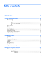
Bottom components ...19 Multimedia components ...20 Wireless antennas (select models only 22 Additional hardware components 23 3 Illustrated parts catalog 24 Service tag ...24 Computer major components 26 Display assembly components 33 Plastics Kit ...35 Cables ...36 Mass storage devices ...37 - Compaq 400 | 320 321 420 421 620 and 621 Notebook PC and 420 and 620 Notebook PC - Page 6
damage 51 Packaging and transporting guidelines 52 Workstation guidelines 52 Equipment guidelines 53 Component replacement procedures 54 Service tag ...54 Computer feet ...55 Battery ...56 Service door ...56 Hard drive ...59 Memory module ...64 WLAN module ...66 Optical drive ...68 Fan ...69 - Compaq 400 | 320 321 420 421 620 and 621 Notebook PC and 420 and 620 Notebook PC - Page 7
Security menu 117 System Configuration menu 118 Computer Setup in Linux ...123 Starting Computer Setup 123 Using Computer Setup 124 Navigating and selecting in Computer Setup 124 Restoring factory settings in Computer Setup 124 Computer Setup menus 125 File menu 125 Security menu 126 - Compaq 400 | 320 321 420 421 620 and 621 Notebook PC and 420 and 620 Notebook PC - Page 8
Recovering your information 146 Recovering the operating system and programs 146 8 Connector pin assignments 148 Audio-in (microphone) ...148 Audio-out (headphone) ...148 External monitor ...149 HDMI ...150 RJ-11 (modem) ...151 RJ-45 (network) ...152 Universal Serial Bus ...152 9 Power cord set - Compaq 400 | 320 321 420 421 620 and 621 Notebook PC and 420 and 620 Notebook PC - Page 9
UMA graphics, GL40 chipset UMA graphics, GM45 chipset Discrete graphics, PM45 chipset Compaq 320 Notebook PC √ √ Compaq 321 Notebook PC Compaq 420 Notebook PC Compaq 421 Notebook PC √ √ √ √ Compaq 620 Notebook PC √ √ Compaq 621 Notebook PC √ HP 420 Notebook PC HP 620 Notebook PC - Compaq 400 | 320 321 420 421 620 and 621 Notebook PC and 420 and 620 Notebook PC - Page 10
allocated) ATI Mobility Radeon HD 530v with 512-MB √ memory ATI Mobility Radeon HD 5470v with 512-MB √ memory All display assemblies support privacy filter √ √ √ 33.8-cm (13.3-in) HD LED backlight panel: √ √ √ ● 1366×768 AntiGlare ● 1366×768 AntiGlare for webcam ● 1366×768 BrightView - Compaq 400 | 320 321 420 421 620 and 621 Notebook PC and 420 and 620 Notebook PC - Page 11
×768 BrightView for Webcam 2 customer-accessible/upgradable memory √ √ √ module slots Supports dual-channel memory √ √ √ Supports up to 4 GB of system RAM √ √ √ PC3-10600, 1333-MHz, DDR3 √ √ √ Supports the following configurations in all √ √ √ countries and regions: ● 4096-MB - Compaq 400 | 320 321 420 421 620 and 621 Notebook PC and 420 and 620 Notebook PC - Page 12
microphone Single speaker Headphone and microphone jacks Integrated 2MP camera with fixed focus (select models only) 56K V.92 3.8 cm (1.5-in) data/fax modem Supports no modem option For use in all countries and regions except APJ For use in APJ only Modem cable not included 10/100 Ethernet network - Compaq 400 | 320 321 420 421 620 and 621 Notebook PC and 420 and 620 Notebook PC - Page 13
11 (modem) √ √ √ RJ-45 (Ethernet, includes link and activity √ √ √ lights) USB 2.0 (3) √ √ √ HP non-Smart adapter √ √ √ VGA (Dsub 15-pin) supporting 1600 × 1200 √ √ √ external resolution at 75-GHz (hot plug/ unplug with auto-detect) Multi-pin AC power √ √ √ HDMI √ √ √ 5 - Compaq 400 | 320 321 420 421 620 and 621 Notebook PC and 420 and 620 Notebook PC - Page 14
√ √ 90-W non-Smart AC adapter √ 6-cell, 47-Wh Li-ion battery √ √ √ 9-cell, 93-Wh Li-ion battery √ √ √ Security Supports Kensington security lock √ √ √ Operating system Preinstalled with Microsoft Office: √ √ √ Windows 7 Home Premium 32 with Office √ √ √ 2010 Starter - EDGI - Compaq 400 | 320 321 420 421 620 and 621 Notebook PC and 420 and 620 Notebook PC - Page 15
Category Description UMA graphics, GL40 chipset UMA graphics, GM45 chipset Discrete graphics, PM45 chipset Windows 7 Professional 32 with Office 2010 √ √ √ Starter - EDGI Windows 7 Professional 64 with Office 2010 √ √ √ Starter (excludes Japan) Windows Vista Home Basic 32 with Office √ - Compaq 400 | 320 321 420 421 620 and 621 Notebook PC and 420 and 620 Notebook PC - Page 16
Category Description UMA graphics, GL40 chipset UMA graphics, GM45 chipset Discrete graphics, PM45 chipset Windows 7 Home Basic 32 with Office 2007 √ √ √ ready (excludes Japan) Windows 7 Home Basic 32 with Office 2010 √ √ √ Starter Windows 7 Home Premium 32 with Office √ √ √ 2010 - Compaq 400 | 320 321 420 421 620 and 621 Notebook PC and 420 and 620 Notebook PC - Page 17
Category Serviceability Description Restore media: Windows 7 Home Basic 32 Windows 7 Home Premium 32 only) DRDVD Windows Vista DRDVD Windows XP Pro Certified: Microsoft® WHQL SuSE Linux Web Support: All Windows Vista 64 versions Windows 7 Professional 64 versions SuSE Linux End-user replaceable - Compaq 400 | 320 321 420 421 620 and 621 Notebook PC and 420 and 620 Notebook PC - Page 18
2 External component identification Top Components TouchPad Component (1) TouchPad * (2) TouchPad button (3) TouchPad scroll zone Description Moves the pointer and selects or activates items on the screen. The left and right sides of the single button function like the left and right buttons on an - Compaq 400 | 320 321 420 421 620 and 621 Notebook PC and 420 and 620 Notebook PC - Page 19
Lights NOTE: Refer to the illustration that most closely matches your computer. Component (1) Caps lock light Description On: Caps lock is on. Top Components 11 - Compaq 400 | 320 321 420 421 620 and 621 Notebook PC and 420 and 620 Notebook PC - Page 20
Component (2) Power light (3) Wireless light Description ● On: The computer is on. ● Blinking: The computer is in the Suspend state. ● Off: The computer is off or in Hibernation. ● White: An integrated wireless device, such as a wireless local area network (WLAN) device is on. ● Amber: All wireless - Compaq 400 | 320 321 420 421 620 and 621 Notebook PC and 420 and 620 Notebook PC - Page 21
Buttons, switch, and speaker Component (1) Speaker (2) Internal display switch (3) Power button Description Produces sound. Turns off the display if the panel lid is closed while the power is on. ● When the computer is off, press the button to turn on the computer. ● When the computer is on, press - Compaq 400 | 320 321 420 421 620 and 621 Notebook PC and 420 and 620 Notebook PC - Page 22
Keys Component (1) esc key (2) fn key (3) Wireless key (4) Function keys (5) Embedded numeric keypad keys Description Displays system information when pressed in combination with the fn key. Executes frequently used system functions when pressed in combination with a function key, the num lk key, - Compaq 400 | 320 321 420 421 620 and 621 Notebook PC and 420 and 620 Notebook PC - Page 23
Component (1) esc key (2) fn key (3) Function keys (4) Embedded numeric keypad keys (5) Wireless key Description Displays system information when pressed in combination with the fn key. Executes frequently used system functions when pressed in combination with a function key, the num lk key, or the - Compaq 400 | 320 321 420 421 620 and 621 Notebook PC and 420 and 620 Notebook PC - Page 24
Front components Component (1) SD Card Reader (2) Audio-out (headphone) jack (3) Audio-in (microphone) jack Right-side components Description Supports the following optional digital card formats: ● MultiMediaCard (MMC) ● MultiMediaCard 4.2 (MMC Plus, including MMC Plus HC) ● Secure Digital (SD) - Compaq 400 | 320 321 420 421 620 and 621 Notebook PC and 420 and 620 Notebook PC - Page 25
Component (4) Optical drive light (select models only) (5) Optical drive button (select models only) Description Blinking: The optical drive is being accessed. Opens the optical drive tray. Right-side components 17 - Compaq 400 | 320 321 420 421 620 and 621 Notebook PC and 420 and 620 Notebook PC - Page 26
cable slot (3) Vent (4) External monitor port (5) Battery light (6) Power connector (7) RJ-45 (network) jack (8) HDMI port (9) USB port (1) Description Supports optional ExpressCards. Attaches an optional security cable to the computer. NOTE: The security cable is designed to act as a deterrent - Compaq 400 | 320 321 420 421 620 and 621 Notebook PC and 420 and 620 Notebook PC - Page 27
Bottom components Component (1) Battery release latches (2) (2) Battery bay Description Release the battery from the battery bay. Holds the battery. Bottom components 19 - Compaq 400 | 320 321 420 421 620 and 621 Notebook PC and 420 and 620 Notebook PC - Page 28
devices in your country. If you replace the module and then receive a warning message, remove the module to restore computer functionality, and then contact technical support. Holds the hard drive. Multimedia components 20 Chapter 2 External component identification - Compaq 400 | 320 321 420 421 620 and 621 Notebook PC and 420 and 620 Notebook PC - Page 29
Component (1) Webcam light (select models only) (2) Webcam (select models only) (3) Integrated microphone (4) Audio-in (microphone) jack (5) Audio-out (headphone) jack (6) Speaker Description On: The webcam is in use. Records audio and video and captures still photographs. Records sound. Connects - Compaq 400 | 320 321 420 421 620 and 621 Notebook PC and 420 and 620 Notebook PC - Page 30
of the Regulatory, Safety and Environmental Notices that applies to your country or region. These notices are located in Help and Support. Component Description (1) WWAN antennas (2)* (select models only) Send and receive wireless signals to communicate with wireless wide-area networks (WWAN - Compaq 400 | 320 321 420 421 620 and 621 Notebook PC and 420 and 620 Notebook PC - Page 31
Additional hardware components Component Description (1) Power cord* Connects an AC adapter to an AC outlet. (2) Battery* Powers the computer when the computer is not plugged into external power. (3) AC adapter Converts AC power to DC power. *Batteries and power cords vary in appearance by - Compaq 400 | 320 321 420 421 620 and 621 Notebook PC and 420 and 620 Notebook PC - Page 32
about the product's hardware components. The part number helps a service technician to determine what components and parts are needed. (4) This is the alphanumeric identifier used to locate documents, drivers, and support for your computer. (5) Warranty period: This number describes the duration of - Compaq 400 | 320 321 420 421 620 and 621 Notebook PC and 420 and 620 Notebook PC - Page 33
Service tag 25 - Compaq 400 | 320 321 420 421 620 and 621 Notebook PC and 420 and 620 Notebook PC - Page 34
Computer major components 26 Chapter 3 Illustrated parts catalog - Compaq 400 | 320 321 420 421 620 and 621 Notebook PC and 420 and 620 Notebook PC - Page 35
Item Description (1) Display assembly (includes microphone, 2 WLAN antenna transceivers and cables and, on select computer models, 2 WWAN antenna transceivers and cables) 39.6-cm (15.6-in) HD AntiGlare display assembly for use in computers equipped without webcam (1366×768 resolution) 605801- - Compaq 400 | 320 321 420 421 620 and 621 Notebook PC and 420 and 620 Notebook PC - Page 36
cm (14.0-in) computers 605776-001 Top cover for HP 39.6-cm (15.6-in) computers 605777-001 Top cover for Compaq 39.6-cm (15.6-in) computers 605778-001 Top cover for Compaq 39.6-cm (15.6-in) computers, red 626093-001 (6) Heat sink For use in computers with UMA graphics subsystems 605749-001 - Compaq 400 | 320 321 420 421 620 and 621 Notebook PC and 420 and 620 Notebook PC - Page 37
Item Description System board with Park XT discrete graphics and RTC battery with PM45 chipset having 1066-MHz FSB (for use in APJ only) 625491-001 System board with UMA graphics and RTC battery with GM45 chipset having 1066-MHz FSB 605747-001 System board with UMA graphics and RTC battery with - Compaq 400 | 320 321 420 421 620 and 621 Notebook PC and 420 and 620 Notebook PC - Page 38
Item Description Celeron® 900, 2.2-GHz,800 MHz FSB, 1-MB cache 534419-001 Pentium T4200, 2.0-GHz, 800 MHz FSB, 1-MB cache 513599-001 Pentium T4300, 2.1-GHz, 800 MHz FSB, 1-MB cache 572929-001 Pentium T4400, 2.2-GHz, 800 MHz FSB, 1-MB cache 584296-001 Core™ 2 Duo, T5870, 2.0-GHz, 800 MHz FSB - Compaq 400 | 320 321 420 421 620 and 621 Notebook PC and 420 and 620 Notebook PC - Page 39
Item Description ● For use in Afghanistan, Albania, Algeria, Andorra, Angola, Antigua and Barbuda, 504593-004 Argentina, Armenia, Aruba, Australia, Austria, Azerbaijan, the Bahamas, Bahrain, Bangladesh, Barbados, Belarus, Belgium, Belize, Benin, Bermuda, Bhutan, Bolivia, Bosnia and Herzegovina - Compaq 400 | 320 321 420 421 620 and 621 Notebook PC and 420 and 620 Notebook PC - Page 40
Item Description 320-GB, 7200-rpm (replaces 614957-001) 320-GB, 7200-rpm for use in 39.6-cm (15.6-in) computers (replaces 614955-001) 250-GB, 7200-rpm (replaces 617441-001) 250-GB, 7200-rpm for use in 39.6-cm (15.6-in) computers 250-GB, 5400-rpm 160-GB, 7200-rpm for use in 39.6-cm (15.6-in) - Compaq 400 | 320 321 420 421 620 and 621 Notebook PC and 420 and 620 Notebook PC - Page 41
bezel with webcam HP 39.6-cm (15.6-in) LCD bezel without webcam HP 39.6-cm (15.6-in) LCD bezel with webcam Compaq 39.6-cm (15.6-in) LCD bezel without webcam Compaq 39.6-cm (15.6-in) LCD bezel with webcam Display Hinge Kit Hinge Kit for 35.6-cm (14.0-in) and 33.8-cm - Compaq 400 | 320 321 420 421 620 and 621 Notebook PC and 420 and 620 Notebook PC - Page 42
spared with display assembly LCD cable LCD cable with webcam 605767-001 LCD cable without webcam 605766-001 Microphone cable Display enclosure For use in Compaq 33.8-cm (13.3-in) computers 605761-001 For use in HP 35.6-cm (14.0-in) computers 605762-001 For use in - Compaq 400 | 320 321 420 421 620 and 621 Notebook PC and 420 and 620 Notebook PC - Page 43
Item Description For use in Compaq 39.6-cm (15.6-in) computers For use in Compaq 39.6-cm (15.6-in) computers, red Plastics Kit Spare part number 605765-001 626094-001 Item (1) (2) Description Plastics Kit: Dummy ExpressCard Dummy optical drive Spare part number 605786-001 Plastics Kit 35 - Compaq 400 | 320 321 420 421 620 and 621 Notebook PC and 420 and 620 Notebook PC - Page 44
Cables Item Description Cable Kit , includes: (1) Bluetooth cable (2) RJ-11 cable (3) Main battery connector Spare part number 605793-001 36 Chapter 3 Illustrated parts catalog - Compaq 400 | 320 321 420 421 620 and 621 Notebook PC and 420 and 620 Notebook PC - Page 45
Item Description (1) WLAN transceiver with cable (2) Microphone cable (3) LCD Cable Kit LCD Cable without webcam ( not shown) LCD Cable with webcam cable (4) USB cable Mass storage devices Spare part number spared with display assembly spared with display assembly 605766-001 605767-001 605796-001 - Compaq 400 | 320 321 420 421 620 and 621 Notebook PC and 420 and 620 Notebook PC - Page 46
Item Description Spare part number 250-GB, 5400-rpm 493994-001 160-GB, 7200-rpm for use in 39.6-cm (15.6-in) computers (replaces 615844-001) 614522-001 160-GB, 7200-rpm 455954-001 160-GB, 7200-rpm 652166-001 (2) Optical drive (includes bezel) DVD±RW Double-Layer Drive with LightScribe - Compaq 400 | 320 321 420 421 620 and 621 Notebook PC and 420 and 620 Notebook PC - Page 47
Miscellaneous parts Description AC adapters 65-W AC adapter for use with computers with UMA graphics 90-W AC adapter for use with computers with discrete graphics Power cords For use in Argentina For use in Australia and New Zealand For use in Brazil For use in Denmark For use in Europe, the Middle - Compaq 400 | 320 321 420 421 620 and 621 Notebook PC and 420 and 620 Notebook PC - Page 48
Sequential part number listing Spare part number Description 449137-001 RTC battery 490371-001 Power cord for use in the United States 490371-021 Power cord for use in Europe, the Middle East, and Africa 490371-031 Power cord for use in the United Kingdom 490371-061 Power cord for use in - Compaq 400 | 320 321 420 421 620 and 621 Notebook PC and 420 and 620 Notebook PC - Page 49
Spare part number Description 513598-001 Intel® Core™ 2 Duo, T6570, 2.1-GHz, 800 MHz FSB, 2-MB cache 513599-001 Intel® Pentium T4200, 2.0-GHz, 800 MHz FSB, 1-MB cache 532324-001 Intel® Celeron® T1600, 1.66-GHz, 800 MHz FSB, 1-MB cache 534084-001 Intel® Celeron® T1700, 1.83-GHz, 800 MHz FSB, 1- - Compaq 400 | 320 321 420 421 620 and 621 Notebook PC and 420 and 620 Notebook PC - Page 50
.6-cm (14.0-in) LCD bezel without webcam 605754-001 HP 35.6-cm (14.0-in) LCD bezel with webcam 605755-001 Compaq 35.6-cm (14.0-in) LCD bezel without webcam 605756-001 Compaq 35.6-cm (14.0-in) LCD bezel with webcam 605757-001 HP 39.6-cm (15.6-in) LCD bezel without webcam 605758 - Compaq 400 | 320 321 420 421 620 and 621 Notebook PC and 420 and 620 Notebook PC - Page 51
TouchPad for HP 39.6-cm (15.6-in) computers (does not include TouchPad board and cable) 605783-001 Palm rest with TouchPad for Compaq 39.6-cm (15.6-in) computers (does not include TouchPad board and cable) 605784-001 Service door for 33.8-cm (13.3-in) and 35.6-cm (14.0-in) computers 605785-001 - Compaq 400 | 320 321 420 421 620 and 621 Notebook PC and 420 and 620 Notebook PC - Page 52
Spare part number Description 605803-001 39.6-cm (15.6-in) HD BrightView display assembly for use in computers without webcam (1366×768 resolution) 605804-001 39.6-cm (15.6-in) HD BrightView display assembly for use in computers with webcam (1366×768 resolution) 605805-001 35.6-cm (14.0-in) HD - Compaq 400 | 320 321 420 421 620 and 621 Notebook PC and 420 and 620 Notebook PC - Page 53
Spare part number Description 605813-261 Keyboard for 35.6-cm (14.0-in) and 33.8-cm (13.3-in) computers for use in Bulgaria 605813-281 Keyboard for 35.6-cm (14.0-in) and 33.8-cm (13.3-in) computers for use in Thailand 605813-291 Keyboard for 35.6-cm (14.0-in) and 33.8-cm (13.3-in) computers for - Compaq 400 | 320 321 420 421 620 and 621 Notebook PC and 420 and 620 Notebook PC - Page 54
Spare part number Description 605814-261 Keyboard for 39.6-cm (15.6-in) computers for use in Bulgaria 605814-281 Keyboard for 39.6-cm (15.6-in) computers for use in Thailand 605814-291 Keyboard for 39.6-cm (15.6-in) computers for use in Japan 605814-A41 Keyboard for 39.6-cm (15.6-in) computers - Compaq 400 | 320 321 420 421 620 and 621 Notebook PC and 420 and 620 Notebook PC - Page 55
) HD BrightView display assembly with LED back lighting for use in computers with WLAN and webcam, red (1366×768 resolution) 616601-001 Top cover for Compaq 33.8-cm (13.3-in) computers, red 623175-001 Display panel AntiGlare, LED back lighting, LVDS for use with 33.8-cm (13.3-in) computers in APJ - Compaq 400 | 320 321 420 421 620 and 621 Notebook PC and 420 and 620 Notebook PC - Page 56
Spare part number Description 652166-001 160-GB, 7200-rpm hard drive 652168-001 Hard drive hardware kit for use with 33.8-cm (13.3-in) and 39.6-cm (14.0-in) computers 652169-001 Hard drive hardware kit for use with 39.6-cm (15.6-in) computers 48 Chapter 3 Illustrated parts catalog - Compaq 400 | 320 321 420 421 620 and 621 Notebook PC and 420 and 620 Notebook PC - Page 57
● Magnetic screwdriver ● Phillips P0 and P1 screwdrivers ● Torx T8 screwdriver Service considerations The following sections include some of the considerations that you must keep in Apply pressure only at the points designated in the maintenance instructions. Preliminary replacement requirements 49 - Compaq 400 | 320 321 420 421 620 and 621 Notebook PC and 420 and 620 Notebook PC - Page 58
Cables and connectors CAUTION: When servicing the computer, be sure that cables are placed in their proper locations during the reassembly process. Improper cable placement can damage the computer. Cables must - Compaq 400 | 320 321 420 421 620 and 621 Notebook PC and 420 and 620 Notebook PC - Page 59
Grounding guidelines Electrostatic discharge damage Electronic components are sensitive to electrostatic discharge (ESD). Circuitry design and structure determine the degree of sensitivity. Networks built into many integrated circuits provide some protection, but in many cases, ESD contains enough - Compaq 400 | 320 321 420 421 620 and 621 Notebook PC and 420 and 620 Notebook PC - Page 60
material. ● Use a wrist strap connected to a properly grounded work surface and use properly grounded tools and equipment. ● Use conductive field service tools, such as cutters, screwdrivers, and vacuums. ● When fixtures must directly contact dissipative surfaces, use fixtures made only of static - Compaq 400 | 320 321 420 421 620 and 621 Notebook PC and 420 and 620 Notebook PC - Page 61
with ground cords of one megohm resistance ● Static-dissipative tables or floor mats with hard ties to the ground ● Field service kits ● Static awareness labels ● Material-handling packages ● Nonconductive plastic bags, tubes, or boxes ● Metal tote boxes ● Electrostatic voltage levels and - Compaq 400 | 320 321 420 421 620 and 621 Notebook PC and 420 and 620 Notebook PC - Page 62
about the product's hardware components. The part number helps a service technician to determine what components and parts are needed. (4) : This is the alphanumeric identifier used to locate documents, drivers, and support for the computer. (5) Warranty period: This number describes the duration of - Compaq 400 | 320 321 420 421 620 and 621 Notebook PC and 420 and 620 Notebook PC - Page 63
Computer feet The computer feet are adhesive-backed rubber pads. The feet are included in the Rubber Kit, spare part number 605789-001 for 33.8-cm (13.3-in) and 35.6-cm (14.0-in) computers and in Rubber Kit 608931-001 for 39.6-cm (15.6-in) computers. There are 4 rubber feet that attach to the base - Compaq 400 | 320 321 420 421 620 and 621 Notebook PC and 420 and 620 Notebook PC - Page 64
latches (1) to release the battery. 3. Remove the battery (2) from the computer. Install the battery by inserting it into the battery bay until you hear a click. Service door Description For use in computers with 39.6-cm (15.6-in) displays For use in computers with 35.6-cm (14-in) and 33.8-cm (13 - Compaq 400 | 320 321 420 421 620 and 621 Notebook PC and 420 and 620 Notebook PC - Page 65
door on a 39.6-cm (15.6-in) computer: 1. Remove four Phillips PM2.0×3.0 screws (1) that secure the service door to the computer. 2. Slide the service door (2) away from the computer. Remove the service door on a 35.6-cm (14-in) or 33.8-cm (13.3-in) computer: 1. Remove two Phillips PM2.0×3.0 screws - Compaq 400 | 320 321 420 421 620 and 621 Notebook PC and 420 and 620 Notebook PC - Page 66
2. Slide the service door (2) away from the computer. Reverse this procedure to install the switch cover. 58 Chapter 4 Removal and replacement procedures - Compaq 400 | 320 321 420 421 620 and 621 Notebook PC and 420 and 620 Notebook PC - Page 67
power cord from the AC outlet and then unplugging the AC adapter from the computer. 4. Remove the battery (see Battery on page 56). 5. Remove the service door (see Service door on page 56). Remove the hard drive from a 39.6-cm (15.6-in) computer: 1. Position the computer right-side up with the front - Compaq 400 | 320 321 420 421 620 and 621 Notebook PC and 420 and 620 Notebook PC - Page 68
4. Remove the hard drive (4) from the hard drive bay. Remove the hard drive from a 35.6-cm (14-in) or 33.8-cm (13.3-in) computer: 1. Position the computer right-side up with the front toward you. 2. Remove the two Phillips PM2.5×6.0 screws (1) and the Phillips PM2.5×4.0 screw (2) that secure the - Compaq 400 | 320 321 420 421 620 and 621 Notebook PC and 420 and 620 Notebook PC - Page 69
To remove the hard drive bracket, follow these steps: 1. If it is necessary to replace the hard drive bracket, remove the two Phillips PM3.0×4.0 hard drive bracket screws (1) from each side of the hard drive. 2. Lift the bracket (2) straight up to remove it from the hard drive. It is necessary to - Compaq 400 | 320 321 420 421 620 and 621 Notebook PC and 420 and 620 Notebook PC - Page 70
For a 35.6-cm (14-in) or 33.8-cm (13.3-in) computer, attach 1 piece of the 90× 8×0.5 mm rubber bumper from spares kit 652168-001 to the outside of the hard drive bracket. For a 35.6-cm (14-in) or 33.8-cm (13.3-in) computers using 7 mm thick hard drives, attach 2 pieces of 13×9.5×3.1 mm rubber bumper - Compaq 400 | 320 321 420 421 620 and 621 Notebook PC and 420 and 620 Notebook PC - Page 71
After the rubber or foam bumpers have been attached, reverse the removal procedure to install the hard drive. Component replacement procedures 63 - Compaq 400 | 320 321 420 421 620 and 621 Notebook PC and 420 and 620 Notebook PC - Page 72
from the AC outlet and then unplugging the AC adapter from the computer. 4. Remove the battery (see Battery on page 56). 5. Remove the service door (see Service door on page 56). Remove the memory module: 1. Position the computer right-side up with the front toward you. 2. Spread the retaining tabs - Compaq 400 | 320 321 420 421 620 and 621 Notebook PC and 420 and 620 Notebook PC - Page 73
3. Remove the memory module (2) by pulling the module away from the slot at an angle. NOTE: Memory modules are designed with a notch to prevent incorrect insertion into the memory module slot. Reverse this procedure to install a memory module. Component replacement procedures 65 - Compaq 400 | 320 321 420 421 620 and 621 Notebook PC and 420 and 620 Notebook PC - Page 74
WLAN module Description Spare part number Broadcom 4312 802.11b/g WLAN modules ● For use in Antigua and Barbuda, Barbados, Belize, Canada, the Cayman Islands, Guam, Puerto Rico, Trinidad and Tobago, the U.S. Virgin Islands, and the United States 504593-003 ● For use in Afghanistan, Albania, - Compaq 400 | 320 321 420 421 620 and 621 Notebook PC and 420 and 620 Notebook PC - Page 75
to restore computer functionality, and then contact technical support through Help and Support. Before removing the WLAN module, follow these steps Remove the battery (see Battery on page 56). 5. Remove the service door (see Service door on page 56). Remove the WLAN module: 1. Disconnect the WLAN - Compaq 400 | 320 321 420 421 620 and 621 Notebook PC and 420 and 620 Notebook PC - Page 76
from the AC outlet and then unplugging the AC adapter from the computer. 4. Remove the battery (see Battery on page 56). 5. Remove the service door (see Service door on page 56). Remove the optical drive: 1. Position the computer with the right side toward you. 2. Remove the Phillips PM2.5×6.0 screw - Compaq 400 | 320 321 420 421 620 and 621 Notebook PC and 420 and 620 Notebook PC - Page 77
from the AC outlet and then unplugging the AC adapter from the computer. 4. Remove the battery (see Battery on page 56). 5. Remove the service door (see Service door on page 56). Remove the fan: 1. Position the computer upside down with the front toward you. 2. Disconnect the fan cable (1) from the - Compaq 400 | 320 321 420 421 620 and 621 Notebook PC and 420 and 620 Notebook PC - Page 78
cord from the AC outlet and then unplugging the AC adapter from the computer. 4. Remove the battery (see Battery on page 56). 5. Remove the service door (see Service door on page 56). 6. Remove the fan (see Fan on page 69). Remove the heat sink on computers with UMA graphics subsystems: 1. Position - Compaq 400 | 320 321 420 421 620 and 621 Notebook PC and 420 and 620 Notebook PC - Page 79
3. Raise the end of the heat sink (3) to free it from the system board components and then remove the heat sink (4) from the system board. Remove the heat sink on computers with discrete graphics subsystems: 1. Position the computer right-side up with the front facing you. 2. Following the sequence - Compaq 400 | 320 321 420 421 620 and 621 Notebook PC and 420 and 620 Notebook PC - Page 80
cord from the AC outlet and then unplugging the AC adapter from the computer. 4. Remove the battery (see Battery on page 56). 5. Remove the service door (see Service door on page 56). 6. Remove the fan (see Fan on page 69). 7. Remove the heat sink (see Heat sink on page 70). Remove the - Compaq 400 | 320 321 420 421 620 and 621 Notebook PC and 420 and 620 Notebook PC - Page 81
the triangle (4) embossed on the processor socket. Reverse this procedure to install the processor. Palm rest Description Palm rest for Compaq units with 39.6-cm (15.6-in) displays (includes TouchPad) Palm rest for Compaq units with 39.6-cm (15.6-in) displays (includes TouchPad), red Palm rest for - Compaq 400 | 320 321 420 421 620 and 621 Notebook PC and 420 and 620 Notebook PC - Page 82
cord from the AC outlet and then unplugging the AC adapter from the computer. 4. Remove the battery (see Battery on page 56). 5. Remove the service door (see Service door on page 56). Remove the palm rest on 39.6-cm (15.6-in) computers: 1. Position the computer upside down with the front toward you - Compaq 400 | 320 321 420 421 620 and 621 Notebook PC and 420 and 620 Notebook PC - Page 83
4. Release the ZIF connector (1) to which the TouchPad cable is connected, and then disconnect the cable (2) from the system board. 5. Remove the palm rest. Remove the palm rest on 35.6-cm (14-in) or 33.8-cm (13.3-in) computers: 1. Position the computer upside down with the front toward you. 2. - Compaq 400 | 320 321 420 421 620 and 621 Notebook PC and 420 and 620 Notebook PC - Page 84
3. Turn the computer over, rotate the palm rest up (1) and slide the palm rest to the right (2) to release it from the computer. 4. Release the ZIF connector (1) to which the TouchPad cable is connected, and then disconnect the cable (2) from the system board. 5. Remove the palm rest. Remove the - Compaq 400 | 320 321 420 421 620 and 621 Notebook PC and 420 and 620 Notebook PC - Page 85
3. Remove the single screw (1) that secures the TouchPad board to the palm rest and lift the TouchPad board (2) from the palm rest. Reverse this procedure to install the TouchPad board. Reverse this procedure to install the palm rest. Component replacement procedures 77 - Compaq 400 | 320 321 420 421 620 and 621 Notebook PC and 420 and 620 Notebook PC - Page 86
cord from the AC outlet and then unplugging the AC adapter from the computer. 4. Remove the battery (see Battery on page 56). 5. Remove the service door (see Service door on page 56). 6. Remove the palm rest (see Palm rest on page 73). Remove the keyboard on 39.6-cm (15.6-in) computers: 1. Position - Compaq 400 | 320 321 420 421 620 and 621 Notebook PC and 420 and 620 Notebook PC - Page 87
3. Turn the unit over, lift the top edge of the keyboard (1) and slide it (2) towards the display. 4. Rest the keyboard on its edge and slide the keyboard back toward the display then, release the ZIF connector (1) to which the keyboard cable is attached, and disconnect the keyboard cable (2) from - Compaq 400 | 320 321 420 421 620 and 621 Notebook PC and 420 and 620 Notebook PC - Page 88
2. Remove two Phillips PM2.5×3.0 broadhead black screws (1), one Phillips PM2.5×3.0 broadhead silver screw (2), and two Torx M2.5×6.0 screws (3) that secure the keyboard. 3. Turn the unit over, lift the top edge of the keyboard (1) and slide it (2) towards the display. 80 Chapter 4 Removal and - Compaq 400 | 320 321 420 421 620 and 621 Notebook PC and 420 and 620 Notebook PC - Page 89
4. Rest the keyboard on its edge and slide the keyboard back toward the display then, release the ZIF connector (1) to which the keyboard cable is attached, and disconnect the keyboard cable (2) from the system board. Reverse this procedure to install the switch cover and keyboard. Component - Compaq 400 | 320 321 420 421 620 and 621 Notebook PC and 420 and 620 Notebook PC - Page 90
Compaq brand computers with 35.6-cm (14.0-in) displays Top cover for use in Compaq brand computers with 33.8-cm (13.3-in) displays Top cover for use in Compaq Remove the battery (see Battery on page 56). 5. Remove the service door (see Service door on page 56). 6. Remove the palm rest (see Palm rest - Compaq 400 | 320 321 420 421 620 and 621 Notebook PC and 420 and 620 Notebook PC - Page 91
Remove the top cover on a 39.6-cm (15.6-in) computer: 1. With the display panel in the open position, press in (1) of the ExpressCard to release it and then pull the card (2) from the computer. 2. Position the computer upside down with the front toward you. 3. Remove the nine Torx M2.5×6.0 screws - Compaq 400 | 320 321 420 421 620 and 621 Notebook PC and 420 and 620 Notebook PC - Page 92
4. Turn the computer over so it is right-side up and remove four Torx M2.5×6.0 screws. 5. Release the ZIF connector (1) and remove the power switch cable (2). 84 Chapter 4 Removal and replacement procedures - Compaq 400 | 320 321 420 421 620 and 621 Notebook PC and 420 and 620 Notebook PC - Page 93
6. Rotate the top cover up (1) and remove it from the base enclosure (2). Remove the top cover on a 35.6-cm (14.0-in) and 33.8-cm (13.3-in) computer: 1. With the display panel in the open position, press in (1) of the ExpressCard to release it and then pull the card (2) from the computer. 2. - Compaq 400 | 320 321 420 421 620 and 621 Notebook PC and 420 and 620 Notebook PC - Page 94
3. Remove the two Phillips PM2.0×2.0 screws (1) located in the battery bay, four Torx M2.5×6.0 screws (2), (3), and (4), and the two Phillips PM2.0×3.0 screws (5) located in the recess near the optical drive. 4. Turn the computer over so it is right-side up and remove five Torx M2.5×6.0 screws. 86 - Compaq 400 | 320 321 420 421 620 and 621 Notebook PC and 420 and 620 Notebook PC - Page 95
5. Release the ZIF connector (1) and disconnect the power switch cable (2). 6. Rotate the top cover up (1) and off the base enclosure (2). Reverse this procedure to install the top cover. Power switch board The spare part number for the power switch board used in all models is 605794-001. Before - Compaq 400 | 320 321 420 421 620 and 621 Notebook PC and 420 and 620 Notebook PC - Page 96
from the AC outlet and then unplugging the AC adapter from the computer. 4. Remove the battery (see Battery on page 56). 5. Remove the service door (see Service door on page 56). 6. Remove the keyboard (see Keyboard on page 78). Remove the power switch board: 1. Release the ZIF connector (1) and - Compaq 400 | 320 321 420 421 620 and 621 Notebook PC and 420 and 620 Notebook PC - Page 97
Bluetooth module NOTE: The Bluetooth module spare part number is 537921-002 and is used in all countries and regions except Japan and Asia Pacific countries and regions. The Bluetooth module cable is included in the Cable Kit, spare part number 605793-001. See Cables on page 36 for more Cable Kit - Compaq 400 | 320 321 420 421 620 and 621 Notebook PC and 420 and 620 Notebook PC - Page 98
2. Disconnect the Bluetooth cable (1) from the system board and remove the antenna (2) from the base enclosure. The antenna is held to the base enclosure with adhesive. Reverse this procedure to install the Bluetooth module. USB connector assembly The spare part number for the USB connector assembly - Compaq 400 | 320 321 420 421 620 and 621 Notebook PC and 420 and 620 Notebook PC - Page 99
3. Remove the Torx M2.5×6.0 screw (3) then, lift the USB connector assembly (4) from the base enclosure. Remove the USB connector assembly on 35.6-cm (14.0-in) and 33.8-cm (13.3-in) computers: 1. Position the computer right-side up with the right side toward you. 2. Release the ZIF connector (1) and - Compaq 400 | 320 321 420 421 620 and 621 Notebook PC and 420 and 620 Notebook PC - Page 100
cord from the AC outlet and then unplugging the AC adapter from the computer. 4. Remove the battery (see Battery on page 56). 5. Remove the service door (see Service door on page 56). 6. Remove the palm rest (see Palm rest on page 73). 7. Remove the keyboard (see Keyboard on page 78). 8. Remove the - Compaq 400 | 320 321 420 421 620 and 621 Notebook PC and 420 and 620 Notebook PC - Page 101
Display assembly Description ● 39.6-cm (15.6-in) HD BrightView display assembly for use in computers equipped with webcam (1366×768 resolution) ● 39.6-cm (15.6-in) HD BrightView display assembly for use in computers without webcam (1366×768 resolution) ● 39.6-cm (15.6-in) HD AntiGlare display - Compaq 400 | 320 321 420 421 620 and 621 Notebook PC and 420 and 620 Notebook PC - Page 102
computer. 4. Remove the battery (see Battery on page 56). 5. Remove the service door (see Service door on page 56). 6. Remove the palm rest (see Palm rest on will comfortably go. CAUTION: Support the display assembly when removing the retaining screws. Failure to support the display assembly can - Compaq 400 | 320 321 420 421 620 and 621 Notebook PC and 420 and 620 Notebook PC - Page 103
in its normal position, face up with the display open as far as it will comfortably go. CAUTION: Support the display assembly when removing the retaining screws. Failure to support the display assembly can result in damage to the display assembly and other computer components. 2. Disconnect the - Compaq 400 | 320 321 420 421 620 and 621 Notebook PC and 420 and 620 Notebook PC - Page 104
3. Release the WLAN cables from the cable run (3), being careful when pulling them through the opening near the hard drive. 4. Remove four Torx M2.5×6.0 screws (1) that secure the display to the base enclosure. Be careful of the grounding cable (2) that is secured by one of the hinge retaining - Compaq 400 | 320 321 420 421 620 and 621 Notebook PC and 420 and 620 Notebook PC - Page 105
Remove the display assembly: 1. If it is necessary to replace the display bezel, display enclosure, or display hinges, remove the two mylar screw covers (1) and the 2 Phillips PM2.5×4.0 screws (2) that secure the display bezel to the display assembly. The screw covers are available in the Rubber Kit - Compaq 400 | 320 321 420 421 620 and 621 Notebook PC and 420 and 620 Notebook PC - Page 106
4. If it is necessary to replace the webcam module, disconnect the webcam cable from the module (1), and pull the webcam module (2) that is attached with adhesive off the display enclosure. The webcam module can be ordered by using spare part number 611026-001. NOTE: To replace the webcam module in - Compaq 400 | 320 321 420 421 620 and 621 Notebook PC and 420 and 620 Notebook PC - Page 107
2. Remove the display hinges (2) by pulling them away from the display panel. The left and right display hinges are available in the Hinge Kit, spare part number 605769-001. Remove the display hinges from 35.6-cm (14.0-in) or 33.8-cm (13.3-in) computers: 1. Remove the six Phillips PM2.0×3.0 screws - Compaq 400 | 320 321 420 421 620 and 621 Notebook PC and 420 and 620 Notebook PC - Page 108
2. Remove the microphone cable from the raceway (2) in the display enclosure. To replace the display cable assembly: 1. Place the display panel face down on a protected soft surface and remove the clear protector (1) that covers the cable connector on the back of the panel. 2. Remove the display - Compaq 400 | 320 321 420 421 620 and 621 Notebook PC and 420 and 620 Notebook PC - Page 109
2. Peel the WLAN antenna receivers (2) from the enclosure Reverse this procedure to assemble the display assembly. Component replacement procedures 101 - Compaq 400 | 320 321 420 421 620 and 621 Notebook PC and 420 and 620 Notebook PC - Page 110
cord from the AC outlet and then unplugging the AC adapter from the computer. 4. Remove the battery (see Battery on page 56). 5. Remove the service door (see Service door on page 56). 6. Remove the hard drive (see Hard drive on page 59). 7. Remove the optical drive (see Optical drive on page 68 - Compaq 400 | 320 321 420 421 620 and 621 Notebook PC and 420 and 620 Notebook PC - Page 111
Remove the system board on a 39.6-cm (15.6-in) computer: 1. Position the computer with the front toward you. 2. Release the audio ZIF connector (1) and disconnect the cable (2) from the left edge of the system board. 3. Remove the two Phillips M2.0×3.0 screws (3) that secure the system board to the - Compaq 400 | 320 321 420 421 620 and 621 Notebook PC and 420 and 620 Notebook PC - Page 112
7. Pull the extender out (2) of the system board and lift it from the base enclosure. 8. Release the RJ-11 cable from the cable routing area, lift the connector from the base enclosure (1), and disconnect the cable (2) from the system board. 9. Disconnect the main battery cable (3) from the bottom - Compaq 400 | 320 321 420 421 620 and 621 Notebook PC and 420 and 620 Notebook PC - Page 113
2. Remove the Phillips PM2.0×3.0 screw (1) that secures the board to the base enclosure, disconnect the audio ZIF connector and remove the flat-ribbon cable (2) from the system board. 3. Remove the optical drive extender on the 35.6-cm (14.0-in) computer by first removing the Phillips PM2.0×3.0 - Compaq 400 | 320 321 420 421 620 and 621 Notebook PC and 420 and 620 Notebook PC - Page 114
cord from the AC outlet and then unplugging the AC adapter from the computer. 4. Remove the battery (see Battery on page 56). 5. Remove the service door (see Service door on page 56). 6. Remove the hard drive (see Hard drive on page 59). 7. Remove the optical drive (see Optical drive on page 68 - Compaq 400 | 320 321 420 421 620 and 621 Notebook PC and 420 and 620 Notebook PC - Page 115
Remove the main battery cable: 1. Remove the two Phillips PM2.5×4.0 screws (1) that secure the connector to the base enclosure. 2. Lift the connector up (2) and out of the base enclosure. Reverse the procedure to install the main battery connector. Component replacement procedures 107 - Compaq 400 | 320 321 420 421 620 and 621 Notebook PC and 420 and 620 Notebook PC - Page 116
cord from the AC outlet and then unplugging the AC adapter from the computer. 4. Remove the battery (see Battery on page 56). 5. Remove the service door (see Service door on page 56). 6. Remove the hard drive (see Hard drive on page 59). 7. Remove the optical drive (see Optical drive on page 68 - Compaq 400 | 320 321 420 421 620 and 621 Notebook PC and 420 and 620 Notebook PC - Page 117
cord from the AC outlet and then unplugging the AC adapter from the computer. 4. Remove the battery (see Battery on page 56). 5. Remove the service door (see Service door on page 56). 6. Remove the hard drive (see Hard drive on page 59). 7. Remove the optical drive (see Optical drive on page 68 - Compaq 400 | 320 321 420 421 620 and 621 Notebook PC and 420 and 620 Notebook PC - Page 118
10. Remove the keyboard (see Keyboard on page 78). 11. Remove the top cover (see Top cover on page 82). 12. Remove the system board (seeSystem board on page 102). Remove the modem module: 1. Position the computer right-side up with the front toward you. 2. Remove the two Phillips PM2.5×3.0 screws - Compaq 400 | 320 321 420 421 620 and 621 Notebook PC and 420 and 620 Notebook PC - Page 119
cord from the AC outlet and then unplugging the AC adapter from the computer. 4. Remove the battery (see Battery on page 56). 5. Remove the service door (see Service door on page 56). 6. Remove the hard drive (see Hard drive on page 59). 7. Remove the optical drive (see Optical drive on page 68 - Compaq 400 | 320 321 420 421 620 and 621 Notebook PC and 420 and 620 Notebook PC - Page 120
2. Remove the Phillips PM2.0×3.0 screw (1) that secures the audio board to the base enclosure and then remove the audio board (2). Remove the audio board from 35.6-cm (14.0-in) and 33.8-cm (13.3-in) computers: 1. Release the latch (1) that secures the board to the base enclosure. 2. Lift the audio - Compaq 400 | 320 321 420 421 620 and 621 Notebook PC and 420 and 620 Notebook PC - Page 121
working or will not load. NOTE: Some of the Computer Setup menu items listed in this guide may not be supported by your computer. NOTE: An external keyboard or mouse connected to a USB port can be Setup screen, press esc, and then follow the on-screen instructions. Computer Setup in Windows 113 - Compaq 400 | 320 321 420 421 620 and 621 Notebook PC and 420 and 620 Notebook PC - Page 122
Computer Setup menus without saving your changes, click the Exit icon in the lower-left corner of the screen, and then follow the on-screen instructions. - or - Use the tab key and the arrow keys to select File > Ignore Changes and Exit, and then press enter. - or - ● To save your changes - Compaq 400 | 320 321 420 421 620 and 621 Notebook PC and 420 and 620 Notebook PC - Page 123
in this section provide an overview of Computer Setup options. NOTE: Some of the Computer Setup menu items listed in this guide may not be supported by your computer. File menu Select System Information Set System Date and Time System Diagnostics Restore defaults Reset BIOS security to factory - Compaq 400 | 320 321 420 421 620 and 621 Notebook PC and 420 and 620 Notebook PC - Page 124
Select Ignore Changes and Exit Save Changes and Exit To do this Cancel any changes entered during the current session. Then exit and restart the computer. Save any changes entered during the current session. Then exit and restart the computer. Your changes go into effect when the computer restarts. - Compaq 400 | 320 321 420 421 620 and 621 Notebook PC and 420 and 620 Notebook PC - Page 125
. NOTE: DriveLock settings are accessible only when you enter Computer Setup by turning on (not restarting) the computer. Enable/disable Automatic DriveLock support (disabled by default). Run Disk Sanitizer to destroy all existing data on the primary hard drive or the drive in the upgrade bay - Compaq 400 | 320 321 420 421 620 and 621 Notebook PC and 420 and 620 Notebook PC - Page 126
System Configuration menu NOTE: Some of the listed System Configuration options may not be supported by your computer. Select Language Boot Options To do this Change the Computer Setup language. ● Set a Startup Menu delay (in seconds). ● Set the MultiBoot Express - Compaq 400 | 320 321 420 421 620 and 621 Notebook PC and 420 and 620 Notebook PC - Page 127
Select Device Configurations To do this ● Enable/disable USB legacy support (enabled by default). When enabled, USB legacy support allows the following: ◦ Use of a USB keyboard in Computer Setup even when a Windows operating system is not running. ◦ Startup from bootable USB devices, including a - Compaq 400 | 320 321 420 421 620 and 621 Notebook PC and 420 and 620 Notebook PC - Page 128
Select To do this NOTE: Availability of these options above varies by computer model. ● Enable/disable secondary battery fast charge (enabled by default). ● Enable/disable HP QuickLook 2 (enabled by default). ● Enable/disable preboot authentication on HP QuickLock boot (enabled by default). ● - Compaq 400 | 320 321 420 421 620 and 621 Notebook PC and 420 and 620 Notebook PC - Page 129
Select Built-In Device Options To do this ● Enable/disable the wireless button state (enabled by default). ● Enable/disable embedded WWAN device (select models only; enabled by default). ● Enable/disable embedded WLAN device (enabled by default). ● Enable/disable embedded Bluetooth® device radio ( - Compaq 400 | 320 321 420 421 620 and 621 Notebook PC and 420 and 620 Notebook PC - Page 130
on next boot. ● Select terminal emulation mode. Options include the following: ◦ ANSI (default setting) ◦ VT100 ● Enable/disable firmware progress event support. ● Enable/disable initiate Intel CIRA. Change, view, or hide security levels for all BIOS menu items. Restore the default security settings - Compaq 400 | 320 321 420 421 620 and 621 Notebook PC and 420 and 620 Notebook PC - Page 131
is not working or will not load. NOTE: Some of the Computer Setup menu items listed in this guide may not be supported by your computer or your operating system. NOTE: Pointing devices are not supported in Computer Setup. You must use the keyboard to navigate and make selections. NOTE: An external - Compaq 400 | 320 321 420 421 620 and 621 Notebook PC and 420 and 620 Notebook PC - Page 132
of the screen. Because Computer Setup is not operating system based, it does not support the TouchPad. Navigation and selection are by keystroke: ● To choose a menu to select File > Save Changes And Exit. Then follow the instructions on the screen. Your preferences go into effect when the computer - Compaq 400 | 320 321 420 421 620 and 621 Notebook PC and 420 and 620 Notebook PC - Page 133
by your computer or your operating system. File menu NOTE: Some of the menu items listed in this section may not be supported by your computer or your operating system. Select System information Restore Defaults Ignore Changes And Exit Save Changes And Exit To do this ● View identification - Compaq 400 | 320 321 420 421 620 and 621 Notebook PC and 420 and 620 Notebook PC - Page 134
, the data on the primary hard drive is destroyed permanently. Diagnostics menu NOTE: Some of the menu items listed in this section may not be supported by your computer or your operating system. Select HDD Self-Test Options Memory Check To do this Run a comprehensive self-test on any hard drive - Compaq 400 | 320 321 420 421 620 and 621 Notebook PC and 420 and 620 Notebook PC - Page 135
hard disk ◦ 6th boot device: Network controller ● Swap the functions of the fn key and left ctrl key. ● Enable/disable USB legacy support. When enabled, USB legacy support allows the following: ◦ Use of a USB keyboard in Computer Setup even when a your operating system is not running. ◦ Startup from - Compaq 400 | 320 321 420 421 620 and 621 Notebook PC and 420 and 620 Notebook PC - Page 136
Select Built-in device options Port options To do this ● Enable/disable embedded WLAN Device Radio. ● Enable/disable embedded Bluetooth Device Radio. ● Enable/disable Network Interface Controller (NIC) ● Enable/disable LAN/WLAN Switching. ● Enable/disable Wake on LAN. ● Enable/disable the - Compaq 400 | 320 321 420 421 620 and 621 Notebook PC and 420 and 620 Notebook PC - Page 137
6 Specifications Computer specifications Metric U.S. Dimensions - 39.6-cm (15.6-in) Depth 24.96 cm 9.83 in Width 37.18 cm 14.6 in Height (front to rear) 2.75 to 3.55 cm 1.09 to 1.40 in Dimensions - 35.6-cm (14.0-in) Depth 22.8 cm 8.98 in Width 32.3 cm 12.67 in Height (front to - Compaq 400 | 320 321 420 421 620 and 621 Notebook PC and 420 and 620 Notebook PC - Page 138
Metric U.S. Operating (not writing to optical disc) 0°C to 35°C 32°F to 95°F Operating (writing to optical disc) 5°C to 35°C 41°F to 95°F Nonoperating -20°C to 60°C -4°F to 140°F Relative humidity Operating 10% to 90% Nonoperating 5% to 95% Maximum altitude (unpressurized) Operating - Compaq 400 | 320 321 420 421 620 and 621 Notebook PC and 420 and 620 Notebook PC - Page 139
Backlight Response Time Total power consumption Viewing angle @CR>10 Metric LED 16 ms 5.6 W (max) 5 VA U.S. 39.6-cm (15.6-in) display specifications 131 - Compaq 400 | 320 321 420 421 620 and 621 Notebook PC and 420 and 620 Notebook PC - Page 140
35.6-cm (14.0-in) display specifications Dimensions Height Width Diagonal Number of colors Contrast ratio Brightness Pixel resolution Format Configuration Backlight Response Time Total power consumption Viewing angle @ CR>10 Metric U.S. 17.40 cm 6.9 in 30.94 cm 12.2 in 35.50 cm 14.0 in 262 - Compaq 400 | 320 321 420 421 620 and 621 Notebook PC and 420 and 620 Notebook PC - Page 141
33.8-cm (13.3-in) display specifications Dimensions Height Width Diagonal Number of colors Contrast ratio Brightness Pixel resolution Format Configuration Backlight Response Time Total power consumption Viewing angle @ CR>10 Metric U.S. 16.50 cm 6.5 in 29.34 cm 11.5 in 33.66 cm 13.3 in 262 - Compaq 400 | 320 321 420 421 620 and 621 Notebook PC and 420 and 620 Notebook PC - Page 142
referring to hard drive storage capacity. Actual accessible capacity is less. Actual drive specifications may differ slightly. NOTE: Certain restrictions and exclusions apply. Contact technical support for details. 134 Chapter 6 Specifications - Compaq 400 | 320 321 420 421 620 and 621 Notebook PC and 420 and 620 Notebook PC - Page 143
DVD-ROM Drive specifications Applicable disc Access time Random Cache buffer Data transfer rate CD-R (24X) CD-RW (10X) CD-ROM (24X) DVD (8X) Multiword DMA mode 2 DVD-ROM (DVD-5, DVD-9, DVD-10, DVD-18, CD-ROM (Mode 1 and 2), CD Digital Audio, CD-XA ready (Mode 2, Form 1 and Form 2), CD-I (Mode 2, - Compaq 400 | 320 321 420 421 620 and 621 Notebook PC and 420 and 620 Notebook PC - Page 144
DVD±RW Double-Layer Combo Drive specifications Applicable disc Access time Random Cache buffer Data transfer rate 24X CD-ROM 8X DVD-ROM 24X CD-R 16X CD-RW 8X DVD+R 4X DVD+RW 8X DVD-R 4X DVD-RW 2.4X DVD+R(9) 5X DVD-RAM Transfer mode Read: Write: CD-DA, CD+(E)G, CD-MIDI, CD-TEXT, CD-ROM, CD-ROM XA - Compaq 400 | 320 321 420 421 620 and 621 Notebook PC and 420 and 620 Notebook PC - Page 145
individual files ● Restoring the computer to a previous state ● Recovering information using recovery tools NOTE: For detailed instructions, perform a search for these topics in Help and Support. NOTE: In case of system instability, HP recommends that you print the recovery procedures and save them - Compaq 400 | 320 321 420 421 620 and 621 Notebook PC and 420 and 620 Notebook PC - Page 146
in your computer. NOTE: DVDs and DVDs with double-layer (DL) support store more information than CDs, so using them for backup reduces the number All Programs > Maintenance > Backup and Restore. 2. Follow the on-screen instructions to set up your backup, create a system image (select models only), - Compaq 400 | 320 321 420 421 620 and 621 Notebook PC and 420 and 620 Notebook PC - Page 147
also use Windows Startup Repair to fix problems that might prevent Windows from starting Restore . 2. Follow the on-screen instructions to recover your entire computer (select Refer to Help and Support for more information. (purchased separately)" section in this guide. 3. If the Windows partition - Compaq 400 | 320 321 420 421 620 and 621 Notebook PC and 420 and 620 Notebook PC - Page 148
Using a Windows 7 operating system DVD (purchased separately)" section in this guide. 3. If the HP Recovery partition is listed, restart the computer, hp.com/support, select your country or region, and follow the on-screen instructions. You can also order the DVD by calling technical support. For - Compaq 400 | 320 321 420 421 620 and 621 Notebook PC and 420 and 620 Notebook PC - Page 149
individual files ● Restoring the computer to a previous state ● Recovering information using recovery tools NOTE: For detailed instructions, perform a search for these topics in Help and Support. NOTE: In case of system instability, HP recommends that you print the recovery procedures and save them - Compaq 400 | 320 321 420 421 620 and 621 Notebook PC and 420 and 620 Notebook PC - Page 150
NOTE: DVDs and DVDs with double-layer (DL) support store more information than CDs, so using them Backup and Restore. 2. Follow the on-screen instructions to back up your entire computer (select models also use Windows Startup Repair to fix problems that might prevent Windows from starting correctly - Compaq 400 | 320 321 420 421 620 and 621 Notebook PC and 420 and 620 Notebook PC - Page 151
Vista operating system DVD (purchased separately)" section in this guide. Using the Windows recovery tools To recover information you previously instructions. NOTE: For additional information on recovering information using the Windows tools, perform a search for these topics in Help and Support - Compaq 400 | 320 321 420 421 620 and 621 Notebook PC and 420 and 620 Notebook PC - Page 152
Using a Windows Vista operating system DVD (purchased separately)" section in this guide. 3. Turn on or restart the computer, and then press esc while hp.com/support, select your country or region, and follow the on-screen instructions. You can also order the DVD by calling technical support. For - Compaq 400 | 320 321 420 421 620 and 621 Notebook PC and 420 and 620 Notebook PC - Page 153
up all files and folders ● Scheduling automatic backups ● Creating recovery points ● Recovering information NOTE: For detailed instructions, perform a search for these topics in Help and Support. NOTE: In case of system instability, HP recommends that you print the recovery procedures and save them - Compaq 400 | 320 321 420 421 620 and 621 Notebook PC and 420 and 620 Notebook PC - Page 154
screen instructions. NOTE: For additional information on initiating a recovery in Windows, perform a search for this topic in Help and Support. . Software, drivers, and updates not installed by HP must be manually reinstalled. To recover your operating system and programs, follow these steps - Compaq 400 | 320 321 420 421 620 and 621 Notebook PC and 420 and 620 Notebook PC - Page 155
Turn on the computer. 5. Follow the on-screen instructions to install the operating system. 6. After the operating system is installed, remove the Operating System disc and insert the Driver Recovery disc. 7. Follow the on-screen instructions to install the drivers and programs. Backup and recovery - Compaq 400 | 320 321 420 421 620 and 621 Notebook PC and 420 and 620 Notebook PC - Page 156
8 Connector pin assignments Audio-in (microphone) Pin Signal 1 Audio signal in 2 Audio signal in 3 Ground Audio-out (headphone) Pin Signal 1 Audio out, left channel 2 Audio out, right channel 3 Ground 148 Chapter 8 Connector pin assignments - Compaq 400 | 320 321 420 421 620 and 621 Notebook PC and 420 and 620 Notebook PC - Page 157
External monitor Pin Signal 1 Red analog 2 Green analog 3 Blue analog 4 Not connected 5 Ground 6 Ground analog 7 Ground analog 8 Ground analog 9 +5 VDC 10 Ground 11 Monitor detect 12 DDC 2B data 13 Horizontal sync 14 Vertical sync 15 DDC 2B clock External monitor 149 - Compaq 400 | 320 321 420 421 620 and 621 Notebook PC and 420 and 620 Notebook PC - Page 158
HDMI Pin 1 2 3 4 5 6 7 8 9 10 11 12 13 14 15 16 17 18 19 Signal Transition minimized differential signal (TMDS) data 2+ TMDS data 2 shield TMDS data 2- TMDS data 1+ TMDS data 1 shield TMDS data 1- TMDS data 0+ TMDS data 0 shield TMDS data 0- TMDS clock+ TMDS clock shield TMDS clockConsumer - Compaq 400 | 320 321 420 421 620 and 621 Notebook PC and 420 and 620 Notebook PC - Page 159
RJ-11 (modem) Pin Signal 1 Unused 2 Tip 3 Ring 4 Unused 5 Unused 6 Unused RJ-11 (modem) 151 - Compaq 400 | 320 321 420 421 620 and 621 Notebook PC and 420 and 620 Notebook PC - Page 160
RJ-45 (network) Pin Signal 1 Transmit + 2 Transmit - 3 Receive + 4 Unused 5 Unused 6 Receive - 7 Unused 8 Unused Universal Serial Bus Pin Signal 1 +5 VDC 2 Data - 3 Data + 4 Ground 152 Chapter 8 Connector pin assignments - Compaq 400 | 320 321 420 421 620 and 621 Notebook PC and 420 and 620 Notebook PC - Page 161
9 Power cord set requirements The wide range input feature of the computer permits it to operate from any line voltage from 100 to 120 volts AC or from 220 to 240 volts AC. The 3-conductor power cord set included with the computer meets the requirements for use in the country or region where the - Compaq 400 | 320 321 420 421 620 and 621 Notebook PC and 420 and 620 Notebook PC - Page 162
Requirements for specific countries and regions Country/region Accredited agency Applicable note number Australia EANSW 1 Austria OVE 1 Belgium CEBC 1 Canada CSA 2 Denmark DEMKO 1 Finland FIMKO 1 France UTE 1 Germany VDE 1 Italy IMQ 1 Japan METI 3 The Netherlands - Compaq 400 | 320 321 420 421 620 and 621 Notebook PC and 420 and 620 Notebook PC - Page 163
contact your local authorities, or see the Electronic Industries Alliance (EIA) Web site at http://www.eiae.org. This section provides disassembly instructions for the display assembly. The display assembly must be disassembled to gain access to the backlight (1) and the liquid crystal display (LCD - Compaq 400 | 320 321 420 421 620 and 621 Notebook PC and 420 and 620 Notebook PC - Page 164
Perform the following steps to disassemble the display assembly: 1. Remove all screw covers (1) and screws (2) that secure the display bezel to the display assembly. 2. Lift up and out on the left and right inside edges (1) and the top and bottom inside edges (2) of the display bezel until the bezel - Compaq 400 | 320 321 420 421 620 and 621 Notebook PC and 420 and 620 Notebook PC - Page 165
4. Disconnect all display panel cables (1) from the display inverter and remove the inverter (2). 5. Remove all screws (1) that secure the display panel assembly to the display enclosure. 6. Remove the display panel assembly (2) from the display enclosure. 7. Turn the display panel assembly upside- - Compaq 400 | 320 321 420 421 620 and 621 Notebook PC and 420 and 620 Notebook PC - Page 166
10. Remove the display panel frame (2) from the display panel. 11. Remove the screws (1) that secure the backlight cover to the display panel. 12. Lift the top edge of the backlight cover (2) and swing it outward. 13. Remove the backlight cover. 14. Turn the display panel right-side up. 158 Chapter - Compaq 400 | 320 321 420 421 620 and 621 Notebook PC and 420 and 620 Notebook PC - Page 167
15. Remove the backlight cables (1) from the clip (2) in the display panel. 16. Turn the display panel upside-down. WARNING! The backlight contains mercury. Exercise caution when removing and handling the backlight to avoid damaging this component and causing exposure to the mercury. 17. Remove the - Compaq 400 | 320 321 420 421 620 and 621 Notebook PC and 420 and 620 Notebook PC - Page 168
18. Remove the backlight from the backlight frame. 19. Disconnect the display panel cable (1) from the LCD panel. 20. Remove the screws (2) that secure the LCD panel to the display rear panel. 21. Release the LCD panel (3) from the display rear panel. 22. Release the tape (4) that secures the LCD - Compaq 400 | 320 321 420 421 620 and 621 Notebook PC and 420 and 620 Notebook PC - Page 169
options 122 AMT setup prompt (Ctrl-P) 122 firmware progress event support. 122 firmware verbosity 122 initiate Intel CIRA 122 termiinal emulation power 13 C Cable Kit contents 36 spare part number 36 cables, service considerations 50 caps lock light, identifying 11 chipset, product description 2 - Compaq 400 | 320 321 420 421 620 and 621 Notebook PC and 420 and 620 Notebook PC - Page 170
keypad 14, 15 wireless 14, 15 L language, changing in Computer Setup 118 latches, battery release 19 LCD Cable contents 37 spare part number 37 legacy support, USB 113, 119, 123, 127 lights caps lock 11 optical drive 17 power 12 webcam 21 wireless 12 M main battery cable removal 106 mass storage - Compaq 400 | 320 321 420 421 620 and 621 Notebook PC and 420 and 620 Notebook PC - Page 171
3 modem module 4 operating system 6 optical drives 4 panels 2 pointing devices 6 ports 5 power requirements 6 processors 1 product name 1 security 6 serviceability 9 wireless 5 product name 1 R recovery partition 140, 143 release latches, battery 19 removal/replacement preliminaries 49 procedures 54 - Compaq 400 | 320 321 420 421 620 and 621 Notebook PC and 420 and 620 Notebook PC - Page 172
description 6 service considerations 49 service door removal 56 spare part numbers 56 service tag, location 24, 54 serviceability, product part numbers 29 USB connector assembly removal 90 spare part number 90 USB legacy support 113, 119, 123, 127 USB port identifying 16, 18 pin assignments 152
-
 1
1 -
 2
2 -
 3
3 -
 4
4 -
 5
5 -
 6
6 -
 7
7 -
8
-
9
-
10
-
11
-
12
-
13
-
14
-
15
-
16
-
17
-
18
-
19
-
20
-
21
-
22
-
23
-
24
-
25
-
26
-
27
-
28
-
29
-
30
-
31
-
32
-
33
-
34
-
35
-
36
-
37
-
38
-
39
-
40
-
41
-
42
-
43
-
44
-
45
-
46
-
47
-
48
-
49
-
50
-
51
-
52
-
53
-
54
-
55
-
56
-
57
-
58
-
59
-
60
-
61
-
62
-
63
-
64
-
65
-
66
-
67
-
68
-
69
-
70
-
71
-
72
-
73
-
74
-
75
-
76
-
77
-
78
-
79
-
80
-
81
-
82
-
83
-
84
-
85
-
86
-
87
-
88
-
89
-
90
-
91
-
92
-
93
-
94
-
95
-
96
-
97
-
98
-
99
-
100
-
101
-
102
-
103
-
104
-
105
-
106
-
107
-
108
-
109
-
110
-
111
-
112
-
113
-
114
-
115
-
116
-
117
-
118
-
119
-
120
-
121
-
122
-
123
-
124
-
125
-
126
-
127
-
128
-
129
-
130
-
131
-
132
-
133
-
134
-
135
-
136
-
137
-
138
-
139
-
140
-
141
-
142
-
143
-
144
-
145
-
146
-
147
-
148
-
149
-
150
-
151
-
152
-
153
-
154
-
155
-
156
-
157
-
158
-
159
-
160
-
161
-
162
-
163
-
164
-
165
-
166
-
167
-
168
-
169
-
170
-
171
-
172
 |
 |

Compaq 320 Notebook PC
Compaq 321 Notebook PC
Compaq 420 Notebook PC
Compaq 421 Notebook PC
Compaq 620 Notebook PC
Compaq 621 Notebook PC
HP 420 Notebook PC
HP 620 Notebook PC
Maintenance and Service Guide