Compaq 400 320 321 420 421 620 and 621 Notebook PC and 420 and 620 Notebook PC - Page 79
Processor, Following the sequence stamped into the heat sink, loosen the captive screws
 |
View all Compaq 400 manuals
Add to My Manuals
Save this manual to your list of manuals |
Page 79 highlights
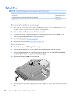
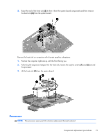
3. Raise the end of the heat sink (3) to free it from the system board components and then remove the heat sink (4) from the system board. Remove the heat sink on computers with discrete graphics subsystems: 1. Position the computer right-side up with the front facing you. 2. Following the sequence stamped into the heat sink, loosen the captive screws (1) and (2) around the processor. 3. Lift the heat sink (3) from the system board. Processor NOTE: The processor spare part kit includes replacement thermal material. Component replacement procedures 71
-
 1
1 -
2
-
3
-
4
-
5
-
6
-
7
-
8
-
9
-
10
-
11
-
12
-
13
-
14
-
15
-
16
-
17
-
18
-
19
-
20
-
21
-
22
-
23
-
24
-
25
-
26
-
27
-
28
-
29
-
30
-
31
-
32
-
33
-
34
-
35
-
36
-
37
-
38
-
39
-
40
-
41
-
42
-
43
-
44
-
45
-
46
-
47
-
48
-
49
-
50
-
51
-
52
-
53
-
54
-
55
-
56
-
57
-
58
-
59
-
60
-
61
-
62
-
63
-
64
-
65
-
66
-
67
-
68
-
69
-
70
-
71
-
72
-
73
-
 74
74 -
 75
75 -
 76
76 -
 77
77 -
 78
78 -
 79
79 -
 80
80 -
 81
81 -
 82
82 -
 83
83 -
 84
84 -
85
-
86
-
87
-
88
-
89
-
90
-
91
-
92
-
93
-
94
-
95
-
96
-
97
-
98
-
99
-
100
-
101
-
102
-
103
-
104
-
105
-
106
-
107
-
108
-
109
-
110
-
111
-
112
-
113
-
114
-
115
-
116
-
117
-
118
-
119
-
120
-
121
-
122
-
123
-
124
-
125
-
126
-
127
-
128
-
129
-
130
-
131
-
132
-
133
-
134
-
135
-
136
-
137
-
138
-
139
-
140
-
141
-
142
-
143
-
144
-
145
-
146
-
147
-
148
-
149
-
150
-
151
-
152
-
153
-
154
-
155
-
156
-
157
-
158
-
159
-
160
-
161
-
162
-
163
-
164
-
165
-
166
-
167
-
168
-
169
-
170
-
171
-
172
 |
 |

3.
Raise the end of the heat sink
(3)
to free it from the system board components and then remove
the heat sink
(4)
from the system board.
Remove the heat sink on computers with discrete graphics subsystems:
1.
Position the computer right-side up with the front facing you.
2.
Following the sequence stamped into the heat sink, loosen the captive screws
(1)
and
(2)
around
the processor.
3.
Lift the heat sink
(3)
from the system board.
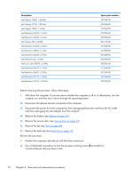
Processor
NOTE:
The processor spare part kit includes replacement thermal material.
Component replacement procedures
71