Craftsman 28813 Operation Manual - Page 25
against adjustment nut.
 |
UPC - 071288130000
View all Craftsman 28813 manuals
Add to My Manuals
Save this manual to your list of manuals |
Page 25 highlights
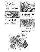
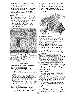
• With an 11/16" or adjustable wrench, loosen jam nut A several turns to clear adjustment nut B. • With a 3/4" or adjustable wrench, turn front link adjustment nut (B) clockwise (tighten)to raisethe front of mower,or, counterclockwise(loosen)to lower the front mower. NOTE: Each full turn of the adjustment nut will change mower height about 1/8". • Recheck measurements,adjust if nec- essary until front tip of blade is 1/8"to 1/2" lower than the rear tip. • Hold adjustment nut in position with wrench and tighten jam nut securely against adjustment nut. 2. Install belt onto electric clutch pulley (M). IMPORTANT: Check belt for proper rout- ing in all mower pulley grooves. 3. Raise attachment lift leverto highest position. TO CHECK BRAKE If tractor requires more than five (5) feet to stop at highest speed in highest gear on a level, dry concrete or paved surface, then brake must be serviced. You may also check brake by: 1. Park tractor on a level, dry concrete or paved surface, depress clutch/brake pedal all the way down and engage parking brake. 2. Place gear shift lever in neutral (N) position. The rear wheels must lock and skid Tighten adjust nut B to raise mower Loosen adjust nut B to lower mower when you try to manually push the tractor forward. If the rear wheels rotate, then the brake needs to be serviced. Contact a Sears or other qualified service center. Loosen jam nut A first TO REPLACE MOWER DRIVE BELT MOWER DRIVE BELT REMOVAL 1. Park tractor on a level surface. Engage parking brake. 2. Lower attachment lift lever to its lowest position. 3. Remove any dirt or grass clippings which may have accumulated around mandrels and entire upper deck surface. 4. Remove belt from electric clutch pulley (M), both mandrel pulleys (R) and all idler pulleys (S). MOWER DRIVE BELT INSTALLATION 1. Install belt around all mandrel pulleys (R) and around idler pulleys (S) as shown. TO REPLACE MOTION DRIVE BELT Park the tractor on level surface. Engage parking brake. For assistance, there is a belt installation guide decal on bottom side of left footrest. BELT REMOVAL- 1. Remove mower (See "TO REMOVE MOWER" in this section of manual). NOTE: Observe entire motion drive belt and position of all belt guides and keepers. 2. Remove belt from stationary idler (A) and clutching idler (B). 3. Pull belt slack toward rear of tractor. . 5. 25 Remove belt upwards from transaxle input pulley (D). Remove belt downward from engine pulley (E). Slide belt toward rear of tractor, off the steering plate (F) and remove from tractor.
-
 1
1 -
2
-
3
-
4
-
5
-
6
-
7
-
8
-
9
-
10
-
11
-
12
-
13
-
14
-
15
-
16
-
17
-
18
-
19
-
 20
20 -
 21
21 -
 22
22 -
 23
23 -
 24
24 -
 25
25 -
 26
26 -
 27
27 -
 28
28 -
 29
29 -
 30
30 -
31
-
32
-
33
-
34
-
35
-
36
-
37
-
38
-
39
-
40
-
41
-
42
-
43
-
44
-
45
-
46
-
47
-
48
-
49
-
50
-
51
-
52
-
53
-
54
-
55
-
56
-
57
-
58
-
59
-
60
-
61
-
62
-
63
-
64
-
65
-
66
-
67
-
68
 |
 |
