Craftsman 536.270320 Owners Manual - Page 7
Assembly - model
 |
View all Craftsman 536.270320 manuals
Add to My Manuals
Save this manual to your list of manuals |
Page 7 highlights
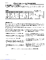
ASSEMBLY PREPARATION The unit is completely assembled except for the items shown in Figure 1, These items are in the carton along with a parts bag The parts bag contains the fasteners needed to complete the assembly of the unit. Find and remove these items Do not discard any parts or material until the unit is assembled 5. Phillips screwdriver 6 Low Tire pressure gauge 7 Knife 8 Socket Set (Optional) HOW TO REMOVE FROM THE CARTON To remove the un!t from the carton, follow the instructions below. 1 Open the top 0{ the carton :' : 2 Remove the wood frame at the top of the carton 3 Cut each corner of the carton from the top to the bottom with a knife Lower the sides of the carton to the ground. 4. Move the shift lever to the neutral (N) position. NOTE: See the Operation section, page 11, for the location of the controls. 5 If the parking brake is engaged, completely push the clutch/brake pedal to release the brake 6, Move the lift lever to the highest position. CAUTION: Check the bottom of the carton for staples, Remove any staples that are in the path of the tires, 7. From the back of the riding mower, carefully pull the riding mower backwards off the wood frame TOOLS YOU NEED TO ASSEMBLE 1 Adjustable wrench (2 required) 2 Open end wrench 1/2" -9/16" 3. Open end wrench 7/16"-'{/2" 4. Blade type screwdriver THE UNIT SteeringWheel -Parts Bag Owner's Manual Seat Bracket Figure 1 MOWER PARTS BAG - CONTENTS The fasteners and other loose parts are shown below The fasteners are shown at full size The quantity is shown in brackets (). On some models, all of the fasteners are not required % lx102 (I) Hex Bolt 5/16"-18x1_/2 " STD523115 2x_53 " (3) Carriage Bolt STD533107 18x1_6 (2) Lockwasher STD551131 54"148 (1) Cover, Battery Terminal lx45 (2) Hex Bolt _/le"-18x5i¢' STD523106 I x38 (2) HexBolt 114"20x518° STD523106 F-99636 15x88 (4) FlangeNut 51t6_-18 STD541431 Q 15x66 (2) Locknut V4%-20 STD541425 91275 (2) Ignition Key Downloaded from www.Manualslib.com manuals search engine
-
 1
1 -
 2
2 -
 3
3 -
 4
4 -
 5
5 -
 6
6 -
 7
7 -
 8
8 -
 9
9 -
 10
10 -
 11
11 -
 12
12 -
13
-
14
-
15
-
16
-
17
-
18
-
19
-
20
-
21
-
22
-
23
-
24
-
25
-
26
-
27
-
28
-
29
-
30
-
31
-
32
-
33
-
34
-
35
-
36
-
37
-
38
-
39
-
40
-
41
-
42
-
43
-
44
-
45
-
46
-
47
-
48
-
49
-
50
-
51
-
52
-
53
-
54
-
55
-
56
-
57
-
58
-
59
-
60
 |
 |
