D-Link DES-5220TF Product Manual
D-Link DES-5220TF - Switch Manual
 |
UPC - 790069220081
View all D-Link DES-5220TF manuals
Add to My Manuals
Save this manual to your list of manuals |
D-Link DES-5220TF manual content summary:
- D-Link DES-5220TF | Product Manual - Page 1
DES-5200 Fast Ethernet Switching System User's Guide Rev. A1 (October, 2004) 651ES5200K15 Printed In Taiwan RECYCLABLE i - D-Link DES-5220TF | Product Manual - Page 2
product's Registration Card, provided at the back of this manual, must be sent to a D-Link office. To obtain an RMA number for warranty service as to a hardware product, or to obtain warranty service as to a software product, contact the D-Link office nearest you. An addresses/ telephone/fax list of - D-Link DES-5220TF | Product Manual - Page 3
such as translation, transformation, or adaptation without permission from D-Link Corporation/D-Link Systems Inc., as stipulated by the United States Copyright Act if not installed and used in accordance with this user's guide, may cause harmful interference to radio communications. Operation of - D-Link DES-5220TF | Product Manual - Page 4
Aerosolreiniger. Am besten dient ein angefeuchtetes Tuch zur Reinigung. Um eine Beschädigung des Gerätes zu vermeiden sollten Sie nur Zubehörteile verwenden, die vom Hersteller Wenden Sie sich mit allen Fragen die Service und Repartur betreffen an Ihren Servicepartner. Somit stellen - D-Link DES-5220TF | Product Manual - Page 5
Table of Contents Table of Contents ...v About This Guide...1 Audience ...1 Organization...1 1...2 Introduction...2 Features ...2 -X Ports ...24 Fiber Optic Ports ...24 RS-232 Port ...24 DES-5200 to DES-5200 Connection ...25 Connecting the DES-5200 to other Switches and Hubs 25 4...26 LEDs ...26 CPU - D-Link DES-5220TF | Product Manual - Page 6
User Account Management ...43 Switch Port Configuration...43 Spanning Tree Configuration ...44 SNMP Management Configuration...44 VLAN Port Management ...44 Trunking Port Management ...44 Port Statistics ...44 Port Monitoring ...44 Broadcast Storm Protection...44 System Configuration Menu...45 - D-Link DES-5220TF | Product Manual - Page 7
Trunking Port Management Menu ...131 Port Statistics ...132 Port Monitoring ...135 Broadcast Storm Protection...137 7...139 Troubleshooting ...139 Appendix A ...144 DES-5200 Technical Specifications 144 Switch Specifications ...144 Port Specifications ...145 Index...149 Registration Card ...152 vii - D-Link DES-5220TF | Product Manual - Page 8
the contents of each chapter. It describes the features of the D-Link DES-5200 Fast Ethernet Switching System. Information about the DES-5200 and other D-Link products is available on our web site at www.dlink.com. Audience This user guide is intended for the networking or computer technician who is - D-Link DES-5220TF | Product Manual - Page 9
with two 12-Port 10/100-TX modules. • The DES-5220TF comes with one 12-Port 10/100-TX module and one 8-Port 100BASE-FX module. • The DES-5216FX comes with two 8-Port 100BASE-FX modules. All DES-5200's have two half size slots that support the following optional modules: • 2-Port 10/100-TX - D-Link DES-5220TF | Product Manual - Page 10
System User's Guide • The DES-5200 can be managed through four methods: Console Management, Telnet Management, SNMP Management and Web Management. • Supports Store-and-Forward switching. • Supports Full and Half Duplex for both 10 Mbps and 100 Mbps. • Supports Spanning Tree Protocol - D-Link DES-5220TF | Product Manual - Page 11
and two are full sized. Slots three and four are halfsized. All slots support modules and can be used simultaneously. All ports can be used for network Link, Inc. sales to purchase modules. Models There are three models available: • The DES-5224TX has two 12-Port 10/100-TX modules. • The DES-5220TF - D-Link DES-5220TF | Product Manual - Page 12
Fast Ethernet Switching System User's Guide Full Size Modules Table 2: DES-5200 Full Size Modules Module Name injury and/or damage. If there is a problem with the modules or the back plane, contact D-Link System, Inc. Technical Support for assistance. Optional Modules The optional modules are - D-Link DES-5220TF | Product Manual - Page 13
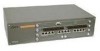
LINE 100-240 VAC 50-60Hz 2.5A MAX. Link Tx/Rx 1x 2x Link Tx/Rx 1x 2x 100 10 3x 4x 100 10 3x 4x 5x 6x 7x 8x 5x 6x 7x 8x 9x 10x 11x 12x 9x 10x 11x 12x Figure 1: DES-5224TX DES-5220TF The DES-5220TF, displayed in Figure 2, comes with one 12 - D-Link DES-5220TF | Product Manual - Page 14
System User's Guide DES-5216FX.A1 The DES-5216FX, displayed in Figure 3, has two 16-Port 100BASE-SX modules. The DES-5216FX is shown with two optional modules, one 2-Port 100BASE-FX module is shown in slot 3 and one 1-Port 1000BASE-SX module is shown in slot 4. Figure 3: DES-5216FX Introduction 7 - D-Link DES-5220TF | Product Manual - Page 15
Fast Ethernet Switching System User's Guide Rear Panel The ventilation fan is located at the rear of the DES-5200, displayed in Figure 4. There are heat vents located on the sides. The fans and the vents help to cool the DES-5200. Always leave two inches of space around the DES-5200 to that air - D-Link DES-5220TF | Product Manual - Page 16
Fast Ethernet Switching System User's Guide Management Methods The DES-5200 supports four management methods: • DES-5200 supports SNMP through D-View, D-Link's proprietary SNMP application and through other vendor's SNMP applications. Please refer to the appropriate documentation for instructions - D-Link DES-5220TF | Product Manual - Page 17
System • RS-232 DCE serial cable • Two mounting brackets and eight screws • Four rubber pads with adhesive backing • One 1.82 m (6 foot) power cord • DES-5200 User's Guide CD ROM, part number 651ES5200K15 • Registration Card If any items are missing, contact the retailer where you purchased the - D-Link DES-5220TF | Product Manual - Page 18
Fast Ethernet Switching System User's Guide Installation Options There are two options for installing the DES-5200: desktop/ shelf installation or rack installation. Follow these guidelines for desktop/ shelf installation or rack installation: • The surface must support 8 kg (18 lbs.) • The power - D-Link DES-5220TF | Product Manual - Page 19
Switching System User's Guide Desktop/ Shelf Installation The dimensions of the DES-5200 are 17.36 inches (441 mm) x 10.39 inches (264 mm) x 4.64 inches (118 mm). These measurements include the 8 mm rubber feet provided with the DES-5200. Follow these steps to install the DES-5200 on a desktop - D-Link DES-5220TF | Product Manual - Page 20
Fast Ethernet Switching System User's Guide Figure 6: Attach Feet Installing the DES-5200 13 - D-Link DES-5220TF | Product Manual - Page 21
Fast Ethernet Switching System User's Guide Rack Installation The DES-5200 can be mounted in an EIA standard size, 19 inch rack. The dimensions of the DES-5200 are 4.4 inches (112 mm) x 10.39 inches (264 mm) x 17.32 inches (440 mm). The DES-5200 can be placed in a wiring closet along with other - D-Link DES-5220TF | Product Manual - Page 22
Fast Ethernet Switching System User's Guide Figure 8: Insert into Rack Installing the DES-5200 15 - D-Link DES-5220TF | Product Manual - Page 23
remove the new module. 3. Install the new module by inserting it into the guides, see Figure 10 and sliding it in until it stops. Press in firmly until that there is a link at the port. See the Troubleshooting section if the optional module is not working properly. Installing the DES-5200 16 - D-Link DES-5220TF | Product Manual - Page 24
Fast Ethernet Switching System User's Guide Figure 9: Remove Blank Bracket Installing the DES-5200 17 - D-Link DES-5220TF | Product Manual - Page 25
Fast Ethernet Switching System User's Guide Figure 10: Insert Optional Module Installing the DES-5200 18 - D-Link DES-5220TF | Product Manual - Page 26
5200. The power LED will light and all ports will auto negotiate the proper speed and duplex mode. Reboot the DES-5200 if there is a problem. Contact D-Link Systems, Inc. for technical support. Check the configuration of the DES-5200 after a power failure but do not reset unless it is necessary. The - D-Link DES-5220TF | Product Manual - Page 27
Guide 3 Connecting the DES-5200 to the Network This chapter covers the following: • Cable Specifications • Ports • Connecting the DES-5200 to another DES-5200 • Connecting the DES . Telephone cable does not support Ethernet or Fast Ethernet. connector. The most common problem on Ethernet or Fast - D-Link DES-5220TF | Product Manual - Page 28
Fast Ethernet Switching System User's Guide The type of cable you use depends on the speed of your network. A network running at 10 Mbps can use 4, and 5 UTP or STP 100BASE-TX Category 3, 4, and 5 UTP or STP Maximum Length 100 M (328 ft.) 100 M (328 ft.) Connecting the DES-5200 to the Network 21 - D-Link DES-5220TF | Product Manual - Page 29
Fast Ethernet Switching System User's Guide Figure 11: Cable Diagram Connecting the DES-5200 to the Network 22 - D-Link DES-5220TF | Product Manual - Page 30
Fast Ethernet Switching System User's Guide Fiber Optic Cable Data can travel much farther over fiber optic cable than over Category 3, 4, or 5 cable. Cable length specified cable: • 62.5 um cable 220 meters (720 feet) • 50 um cables 500 meters (1639 feet) Connecting the DES-5200 to the Network 23 - D-Link DES-5220TF | Product Manual - Page 31
User's Guide Ports MDI SX module only supports full duplex at 1000 Mbps. Refer to Installing Optional Modules for installation instructions. Refer to proper speed and duplex mode. RS-232 Port Follow these steps to connect the DES-5200 and another device: 1. Plug one end of the cable provided into the - D-Link DES-5220TF | Product Manual - Page 32
Fast Ethernet Switching System User's Guide DES-5200 to DES-5200 Connection Two or more DES-5200s can be connected together through one or more media ports. When connecting multiple ports to another DES-5200 use port trunking for better performance. When bandwidth aggregation is desired, connect - D-Link DES-5220TF | Product Manual - Page 33
Switching System User's Guide 4 LEDs The LED panel is designed to enable you to manage the DES-5200 at a glance. The LEDs on each module are dealt with in detail. The LEDs indicate the following: • Power • Status • Diagnostic • Utilization • TxRx • Link • 100/10 • Link/ TxRx • Duplex • Collision - D-Link DES-5220TF | Product Manual - Page 34
dark during normal operation. Diagnostic The Diagnostic LED is used to diagnose any problems on the DES-5200. If any part of the DES-5200 fails the POST or if a problem occurs the Diagnostic LED displays a code indicating the problem. See Chapter 6 for the meaning of the LED code and a recommended - D-Link DES-5220TF | Product Manual - Page 35
Guide Table 6: CPU Module LEDs LED Status Diagnostic Utilization Lit or Flashing Status LED increments when firmware is being loaded to the DES- Normal if there are no problems. See Chapter 7 for a chart showing the meaning of the Diagnostic LED. Check Diagnostic LED if the DES-5200 is on and - D-Link DES-5220TF | Product Manual - Page 36
Fast Ethernet Switching System User's Guide 12-Port 10/100-TX Module This section covers the port and the Link LED is off, check the cable and connection. The default value is that all ports auto-negotiate the proper speed and duplex mode. If the port has been manually configured for a particular - D-Link DES-5220TF | Product Manual - Page 37
Fast Ethernet Switching System User's Guide Table 7: 12-Port 10/100-TX Module LEDs LED Link 100 10 Green Green indicates port speed is 100 Mbps LED flashes when there is activity. Port is working at 100 Mbps Dark No link or link is down Port is working at 10 Mbps LEDs 30 - D-Link DES-5220TF | Product Manual - Page 38
Fast Ethernet Switching System User's Guide 2-Port 10/100-TX Module The LEDs on the 2-Port 10/100-TX Module are different than on the 12-Port 10/100-TX Module. Refer to Table 8: 2-Port Tx Module LEDs. 10/100 Tx Link Rx FDX Figure 15: 2-Port 10/100-TX Module 100/10 - D-Link DES-5220TF | Product Manual - Page 39
System User's Guide Col Col means collision. The Col LED is amber when collisions occur at the port. Collisions are normal on the network. You should be concerned when a high number of collisions happen at the port. Table 8: 2-Port Tx Module LEDs LED 100/10 (Speed) (Green) Link (Link) (Green) FDX - D-Link DES-5220TF | Product Manual - Page 40
Fast Ethernet Switching System User's Guide 8-Port FX Module This section covers the LEDs on the 8-Port FX Module, displayed in Figure 16. Refer to Table 9: 8-Port FX Module LEDs. Figure 16: 8-Port FX Module Link Tx/ Rx Indicates there is a link between devices at a specific port and that there - D-Link DES-5220TF | Product Manual - Page 41
Switching System User's Guide 2-Port 100BASE-FX Module Link Transmitting Receiving Collision Figure link at the port. Dx Dx means duplex mode. The Dx LED indicates the port's duplex mode. The ports will not auto negotiate the duplex mode. The default value is half duplex. They can be manually - D-Link DES-5220TF | Product Manual - Page 42
Fast Ethernet Switching System User's Guide Table 10: FX Module LED LED Lk (Link) (Green) Dx (Duplex mode) (Green) Tx (Transmitting) (Green) Rx (Receiving) (Green) Col (collisions) (Amber) Lit Port is linked to another device Port is in full duplex Port is transmitting data Data is being received - D-Link DES-5220TF | Product Manual - Page 43
Fast Ethernet Switching System User's Guide 1-Port 1000BASE-SX Module Ac t Link 1000BASE-SX Switched ports module Figure 18: 1-port 1000BASE-SX Module The gigabit module, displayed in Figure 18, has one port. Refer to Table 11: Gigabit Module LED. Link The Link LED lights to indicate there is a - D-Link DES-5220TF | Product Manual - Page 44
Guide 5 Console Based Management This chapter covers three types of management: • Console Management (out-of-band) • Telnet Management (in-band) • D-View/ SNMP Management Web management is covered in Chapter 6. The DES DES-5200. The DES-5200 supports SNMP applications. All instructions given in this - D-Link DES-5220TF | Product Manual - Page 45
Fast Ethernet Switching System User's Guide Console Management Console Management is always done through the RS-232 serial port and requires a direct connection between the DES-5200 and a PC. This type of management is very useful when the network is down and the DES-5200 cannot be reached by any - D-Link DES-5220TF | Product Manual - Page 46
Guide Telnet Management You can manage the DES-5200 via Telnet session. However, first you must assign a unique IP address to the DES-5200. Use Console Management to log into the DES IP address. Once you have assigned an IP address to the DES-5200, you can use the management method of your choice. - D-Link DES-5220TF | Product Manual - Page 47
Guide Log In The Log In panel, displayed in Figure 19, is the first panel you see when connecting to the DES-5200. All management methods require you to log into the DES Password. Figure 19: Login Follow these steps to log into the DES-5200 for the first time: Enter the default User Name and - D-Link DES-5220TF | Product Manual - Page 48
Fast Ethernet Switching System User's Guide Help Message A one page panel, displayed in Figure 20, is available. The menu lists the keystroke and typographic conventions available on the DES-5200. Figure 20: Help Message Managing the DES-5200 41 - D-Link DES-5220TF | Product Manual - Page 49
Fast Ethernet Switching System User's Guide Panel Conventions Keystroke Conventions Example UP, DOWN, or TAB keys SPACEBAR DEL, or BACKSPACE LEFT or RIGHT keys Ctrl-r Warning Message. After you are finished viewing the help panel, press Enter to return to the main menu. Managing the DES-5200 42 - D-Link DES-5220TF | Product Manual - Page 50
Guide Console Program The Console Program, shown in Figure 21, is the main menu of the DES-5200. Figure 21: Console Program System Configuration The System configuration menu shows general information about the DES may be different, depending on the DES-5200 model you purchased and the modules - D-Link DES-5220TF | Product Manual - Page 51
Fast Ethernet Switching System User's Guide Spanning Tree Configuration The menu enables you to enable or disable Spanning Tree Algorithm, set the Bridge Priority, Hello Time, a menu: 1. Use the tab key or the up and down arrow keys to select an option. 2. Press Enter. Managing the DES-5200 44 - D-Link DES-5220TF | Product Manual - Page 52
Fast Ethernet Switching System User's Guide System Configuration Menu Managing the DES-5200, displayed in Figure 22, enables you to change the configuration of the DES-5200. Figure 22: System Configuration Menu System Information The System Information menu displays the Hardware Revision, MAC - D-Link DES-5220TF | Product Manual - Page 53
Fast Ethernet Switching System User's Guide Software Update There are two ways to update software: XMODEM and TFTP. XMODEM requires a direct connection between the DES-5200 and a PC. TFTP is done through Telnet and can be done from a remote location using a TFTP server. Ping Ping enables users to - D-Link DES-5220TF | Product Manual - Page 54
holds 44 characters. System Contact Specifies the group or individual to contact if there is a problem with the DES5200. The field holds 44 characters. System Up Time Indicates the length of time the DES-5200 has been running without being rebooted. LAN IP Address Specifies the unique IP address of - D-Link DES-5220TF | Product Manual - Page 55
without powering off. Figure 24: System Reset Some configurations require that the DES-5200 be reset in order for them to take effect. Screen prompts instruct you to reset as needed. Follow these steps to reset the DES-5200: 1. Select Yes. 2. Press Enter. To exit without resetting: 1. Select No - D-Link DES-5220TF | Product Manual - Page 56
Fast Ethernet Switching System User's Guide 2. Press Enter. Managing the DES-5200 49 - D-Link DES-5220TF | Product Manual - Page 57
Fast Ethernet Switching System User's Guide Factory Reset The Factory Reset panel, displayed in Figure 25, is used to reset the DES-5200 and restore all factory default values. Using this panel erases all configurations and customization. Figure 25: Factory Reset Follow these steps to restore - D-Link DES-5220TF | Product Manual - Page 58
User's Guide Switch Control Switch Control, displayed in Figure 26, enables you to set the Address Aging. Figure 26: System Rate Control Rate Control Store and Forward is a global setting that affects all the ports except the RS-232 port. Store and Forward means that when the DES-5200 receives - D-Link DES-5220TF | Product Manual - Page 59
Fast Ethernet Switching System User's Guide Store and Forward requires more memory because the DES-5200 must store the packet either XMODEM or TFTP. XMODEM requires a direct physical connection between a PC and the DES-5200. TFTP requires a TFTP server and that you know the Internet Protocol (IP - D-Link DES-5220TF | Product Manual - Page 60
Fast Ethernet Switching System User's Guide Figure 27: Software Update Configuration Follow these steps to download using XMODEM: 1. shows elapsed time and other information about the software update. 6. Reset the DES-5200 when you see the final update panel, displayed in Figure 31. Managing the - D-Link DES-5220TF | Product Manual - Page 61
Fast Ethernet Switching System User's Guide Figure 28: Software Update Confirmation Figure 29: Send File Managing the DES-5200 54 - D-Link DES-5220TF | Product Manual - Page 62
Fast Ethernet Switching System User's Guide Figure 30: XMODEM Figure 31: EEPROM Managing the DES-5200 55 - D-Link DES-5220TF | Product Manual - Page 63
Guide TFTP TFTP is done using Telnet. It can be done from a remote location using a TFTP server. The TFTP server and the DES-5200 must be on the same subnet. For example, if the IP address of the DES digits will be unique to the server and the DES-5200. Remember that two devices cannot have the same - D-Link DES-5220TF | Product Manual - Page 64
Fast Ethernet Switching System User's Guide Figure 33: TFTP Transfer Complete Managing the DES-5200 57 - D-Link DES-5220TF | Product Manual - Page 65
Guide Ping Ping, shown in Figure 34, is a utility to determine if a specific IP address is accessible. Ping sends a packet to the specified address and waits for a reply. Its primary purpose is to troubleshoot IP address the reply came from, bytes, sequence and port number. Managing the DES-5200 58 - D-Link DES-5220TF | Product Manual - Page 66
Fast Ethernet Switching System User's Guide An unsuccessful ping results in a request timed out and gives the sequence number. Managing the DES-5200 59 - D-Link DES-5220TF | Product Manual - Page 67
Fast Ethernet Switching System User's Guide User Account Management The User Account Management panels enable you to add users, delete users and modify user Figure 35: User Account Change Follow these steps to select a menu option: 1. Select an option. 2. Press Enter. Managing the DES-5200 60 - D-Link DES-5220TF | Product Manual - Page 68
Fast Ethernet Switching System User's Guide Create New User The Create New User panel, displayed in Figure 36, enables you to add new users. You can have a total of three users on the DES-5200. Figure 36: Create New User User Name Enter the user's name in this field. User names are case - D-Link DES-5220TF | Product Manual - Page 69
Fast Ethernet Switching System User's Guide General Users have read only access to the DES-5200. They can look at the panels but they cannot make any changes to existing settings or configurations bar to set the access level of the new user. 5. Select Save and press Enter. Managing the DES-5200 62 - D-Link DES-5220TF | Product Manual - Page 70
Fast Ethernet Switching System User's Guide Delete Users The Delete Users panel, displayed in Figure 37, enables you to delete users from the DES-5200. As a safety precaution, the DES-5200 will not enable the user who is currently logged in to delete themselves by accident. Figure 37: Delete Users - D-Link DES-5220TF | Product Manual - Page 71
Fast Ethernet Switching System User's Guide Follow these steps to change user Access Level: 1. Select the user's Access Level. 2. Toggle the space bar to change the current the space bar to toggle the option from No to Yes. 3. Press Enter. 4. Select Save and press Enter. Managing the DES-5200 64 - D-Link DES-5220TF | Product Manual - Page 72
Fast Ethernet Switching System User's Guide Change Password The Change Password panel, displayed in Figure 38, enables you to change user passwords. Figure 38: Change Enter the user's name in the User Name field. 2. Enter the user's old password in the Old Password field. Managing the DES-5200 65 - D-Link DES-5220TF | Product Manual - Page 73
Fast Ethernet Switching System User's Guide 3. Enter the new password in the New Password field. 4. Reenter the new password in the Confirm Password field. 5. Select Save and press Enter to save your changes. Managing the DES-5200 66 - D-Link DES-5220TF | Product Manual - Page 74
Fast Ethernet Switching System User's Guide Switch Port Configuration The Switch Port Configuration panels are used to configure individual ports on the DES-5200. The only difference between the panels is the port number that they deal with. The options and settings are the same for each. Select - D-Link DES-5220TF | Product Manual - Page 75
Ethernet Switching System User's Guide Switch Port Configuration Menu The Physical Refers to the physical state of the port. If the port state is manually changed it will not change states. It will not auto negotiate speed and duplex mode the gigabit module is installed. Managing the DES-5200 68 - D-Link DES-5220TF | Product Manual - Page 76
supported. link is connected at 100 Mbps full duplex • 1000SX Full Duplex indicates the link is connected at 1000 Mbps full duplex Follow these steps to change the port state: 1. Select the State setting of the appropriate port. 2. Toggle the space bar to change the current setting. Managing the DES - D-Link DES-5220TF | Product Manual - Page 77
Fast Ethernet Switching System User's Guide 3. Select Save and press Enter. Follow these steps to change a port's physical state: 1. Select the physical setting of the of the appropriate port. 2. Enter a new value between zero and 255. 3. Select Save and press Enter. Managing the DES-5200 70 - D-Link DES-5220TF | Product Manual - Page 78
Guide Spanning Tree Configuration The Spanning Tree Configuration panel is used to configure the Spanning Tree Algorithm. The Spanning Tree Algorithm (STA) in the DES network. These backup paths are idle until the DES-5200 determines that a problem has developed in the primary path. If the primary - D-Link DES-5220TF | Product Manual - Page 79
Guide Spanning Tree Algorithm Spanning Tree Algorithm can be enabled or disabled. Use Spanning Tree to prevent network loops. Bridge Priority The Bridge Priority can be from 0 to 65535. Zero is the highest Bridge Priority. The higher the Bridge Priority the greater the chance that the DES manually, - D-Link DES-5220TF | Product Manual - Page 80
) > Max Age, 2 x (Hello Time plus 1 second) < Max Age Enable or disable LAN segment Increases chance of becoming the Root Port Disable a port for security or problem isolation No comment Managing the DES-5200 73 - D-Link DES-5220TF | Product Manual - Page 81
Guide SNMP Management Configuration The SNMP Management Configuration panel is used to configure the DES-5200 for SNMP management. Leave the default values in place if you are not managing your network through SNMP. The DES based network manager. The DES-5200 supports its own proprietary enterprise - D-Link DES-5220TF | Product Manual - Page 82
Fast Ethernet Switching System User's Guide SNMP Management Configuration Menu The SNMP Management Configuration menu, displayed in Figure 41, enables you to configure the DES-5200 for SNMP management. Figure 41: SNMP Management Configuration menu SNMP Manager Setting The fields under this setting - D-Link DES-5220TF | Product Manual - Page 83
Failure Signifies that an addressee (or manager/ user) on the DES-5200 is not a valid user of the DES-5200 and may have entered an incorrect community name. Link Change Event Signifies that the link of a port has changed from link up to link down or vice versa. IP Address This field is used to - D-Link DES-5220TF | Product Manual - Page 84
Fast Ethernet Switching System User's Guide SNMP Community String Enter the Community String of the Trap Managers in this field. Status The DES-5200 will not send out traps unless the status is Valid. Follow these to select Valid or Invalid. 4. Select Save and press Enter. Managing the DES-5200 77 - D-Link DES-5220TF | Product Manual - Page 85
Fast Ethernet Switching System User's Guide VLAN Port Management A Virtual Local Area Network (VLAN) is a are not already on their own LAN segment. VLANs can be used to subdivide the network. The DES-5200 supports port based VLAN. Port based VLAN means that the VLAN is grouped by port. If a VLAN - D-Link DES-5220TF | Product Manual - Page 86
Fast Ethernet Switching System User's Guide VLAN Port Management Menu The VLAN Port Management menu, displayed in Figure 42, enables you to create, delete and modify VLANs on the DES-5200. Figure 42: VLAN Port Management menu Follow these steps to create, delete and modify VLAN: 1. Select the - D-Link DES-5220TF | Product Manual - Page 87
Fast Ethernet Switching System User's Guide Create New VLAN The Create New VLAN menu, displayed in Figure 43, is used to create a new VLAN. The default value is that the port has been assigned to. The field is open if the port has not been assigned to a Trunk Group. Status Managing the DES-5200 80 - D-Link DES-5220TF | Product Manual - Page 88
Fast Ethernet Switching System User's Guide The Status field can be either available or selected. Available indicates that the port is available for inclusion in a VLAN. toggle the space bar to change the status from Available to Selected. 3. Select Save and press Enter. Managing the DES-5200 81 - D-Link DES-5220TF | Product Manual - Page 89
Fast Ethernet Switching System User's Guide Delete VLAN Menu The Delete VLAN menu, displayed in Figure 44, is used to delete VLANs. the VLAN. 3. Select Save and press Enter. 4. A screen prompt will warn you that you must reset the DES-5200 in order for the change to take effect. Managing the - D-Link DES-5220TF | Product Manual - Page 90
Fast Ethernet Switching System User's Guide Modify VLAN Menu The Modify VLAN menu, displayed in Figure 45, enables you to modify VLANs. Figure 45: Modify VLAN menu means the port has been selected as part of a VLAN. 5. Select Save and press Enter to implement your changes. Managing the DES-5200 83 - D-Link DES-5220TF | Product Manual - Page 91
Fast Ethernet Switching System User's Guide Trunking Port Management Menu The Trunking Port Management panels, displayed in Figure 46, are used to create, delete Follow these steps to create, delete and modify trunk ports: 1. Select the appropriate option. 2. Press Enter. Managing the DES-5200 84 - D-Link DES-5220TF | Product Manual - Page 92
Fast Ethernet Switching System User's Guide Create New Trunking Port The Create New Trunking Port panel, displayed in Figure 47, is used to create Trunk Ports. You can the port has been assigned to. The field is open if the port has not been assigned to a TrunkGroup. Status Managing the DES-5200 85 - D-Link DES-5220TF | Product Manual - Page 93
Fast Ethernet Switching System User's Guide The status field can be either available or selected. Available indicates that the port is available for inclusion in a toggle the space bar to change the status from available to Selected. 3. Select Save and press Enter. Managing the DES-5200 86 - D-Link DES-5220TF | Product Manual - Page 94
Fast Ethernet Switching System User's Guide Delete Trunking Port The Delete Trunking Port panel, displayed in Figure 48, is used to delete Trunk Ports. Figure 48: Delete column. 2. Toggle the space bar to Yes to delete the Trunking Group. 3. Select Save and press Enter. Managing the DES-5200 87 - D-Link DES-5220TF | Product Manual - Page 95
Fast Ethernet Switching System User's Guide Modify Trunking Port The Modify Trunking port panel, displayed in Figure 49, enables you to Modify Trunking Ports. are not available for inclusion in any trunking group. 5. Select Save and press Enter to implement your changes. Managing the DES-5200 88 - D-Link DES-5220TF | Product Manual - Page 96
Fast Ethernet Switching System User's Guide Port Statistics The Port Statistics panel, displayed in Figure 50, shows statistical information about each port. Figure Out Number of multicast frames transmitted. Tx Broadcast Frames Out Number of broadcast frames transmitted. Managing the DES-5200 89 - D-Link DES-5220TF | Product Manual - Page 97
Fast Ethernet Switching System User's Guide Tx Aged Frames Number of frames dropped because they were in transmit too long. Tx FCS Errors Number of Frames In Number of unicast frames received. Rx Multicast Frames Number of multicast frames received. Rx Broadcast Frames Managing the DES-5200 90 - D-Link DES-5220TF | Product Manual - Page 98
Fast Ethernet Switching System User's Guide Number of broadcast frames received. Rx Good Oversized Number of good oversized frames received. Rx Error Oversized Number of good long. Rx Disc Mem Full Number of good frames that were discarded because the memory was full. Managing the DES-5200 91 - D-Link DES-5220TF | Product Manual - Page 99
Fast Ethernet Switching System User's Guide Port Monitoring The Port Monitoring panel, shown in Figure 51, is used to gather information about ports. The panel is disabled. Monitoring Port The port that receives the monitoring data. Monitored Port The port being monitored. Managing the DES-5200 92 - D-Link DES-5220TF | Product Manual - Page 100
Fast Ethernet Switching System User's Guide Monitored Data Selecting Transmitted monitors all outgoing packets. • Broadcast monitors only broadcast packets. • Discard monitors all packets discarded by the DES-5200. Follow these steps to configure port monitoring: 1. Toggle the space bar to Enable - D-Link DES-5220TF | Product Manual - Page 101
Fast Ethernet Switching System User's Guide Broadcast Storm Protection Broadcast Storm Protection, shown in Figure 52, protects the LAN from being downed by a broadcast storm. 3000 packets per second or more. The port will remain blocked until the number of data packets Managing the DES-5200 94 - D-Link DES-5220TF | Product Manual - Page 102
Fast Ethernet Switching System User's Guide received drops below 3000 packets per second and then it returns to normal. • Block&Trap blocks the port and sends a message to the SNMP Trap Manager that a specific port is being partitioned from the rest of the DES-5200. You must configure the SNMP Trap - D-Link DES-5220TF | Product Manual - Page 103
Fast Ethernet Switching System User's Guide 6 Web Management The DES-5200 can be managed through an Internet connection. Management. Using Web Management You can use your web browser to configure and manage the DES-5200. The DES-5200 must have an IP address in order to be managed over the web. Log - D-Link DES-5220TF | Product Manual - Page 104
Fast Ethernet Switching System User's Guide Logging In The Login panel, shown in Figure 53 and Figure 54, appears when you log in over the web. The user name and password - D-Link DES-5220TF | Product Manual - Page 105
Fast Ethernet Switching System User's Guide Figure 54: User Name and Password Web Management 98 - D-Link DES-5220TF | Product Manual - Page 106
System User's Guide System Configuration The System Information panel is the first panel you see when logging into the DES-5200 for make other changes. The panels and options may be different, depending on the DES-5200 model you purchased and the modules you have installed. Refer to Module - D-Link DES-5220TF | Product Manual - Page 107
Fast Ethernet Switching System User's Guide VLAN Port Management The VLAN Port Management menu enables you to create, delete, and modify VLANs quickly and easily. Trunking Port Management The Trunking Port - D-Link DES-5220TF | Product Manual - Page 108
Fast Ethernet Switching System User's Guide Follow these steps to select a menu: 1. Click on the Software can be updated in two ways: XMODEM and TFTP. XMODEM requires a physical connection between the DES-5200 and a workstation. TFTP can be done remotely. When updating software over the web, TFTP is - D-Link DES-5220TF | Product Manual - Page 109
Fast Ethernet Switching System User's Guide System Information Menu The System Information menu, displayed in Figure 55, enables you to enter management and configuration information on the DES-5200. Figure 55: System Information Hardware Revision Specifies the hardware revision and the product - D-Link DES-5220TF | Product Manual - Page 110
up to 44 characters. System Contact Specifies the group or individual to contact if there is a problem with the DES5200. The filed holds 44 characters. System Up Time Indicates the length of time the DES-5200 has been running without being rebooted. LAN IP Address Specifies the unique IP address of - D-Link DES-5220TF | Product Manual - Page 111
Fast Ethernet Switching System User's Guide System Reset The System Reset panel, displayed in Figure 56, enables you to reset the DES5200 without powering off. Figure 56: System Reset Some configurations will require you to reset the DES-5200 in order for them to take effect. Screen prompts will - D-Link DES-5220TF | Product Manual - Page 112
Fast Ethernet Switching System User's Guide Factory Reset The Factory Reset panel, displayed in Figure 57, is used to reset the DES-5200 and restore all factory default values. Using this panel erases all configurations and customization. A confirmation panel appears, displayed in Figure 58, when - D-Link DES-5220TF | Product Manual - Page 113
Fast Ethernet Switching System User's Guide Figure 58: Factory Reset Confirmation Follow these steps to restore factory default configurations: 1. Select Apply. To exit without resetting: 1. Select another menu to exit. Web Management 106 - D-Link DES-5220TF | Product Manual - Page 114
Fast Ethernet Switching System User's Guide Switch Control The Switch Control panel, displayed in Figure 59, enables you to set the packet forwarding rate on the DES-5200. Figure 59: Switch Control Rate Control Store and Forward means that when the DES-5200 receives an incoming packet it "stores" - D-Link DES-5220TF | Product Manual - Page 115
Fast Ethernet Switching System User's Guide Store and Forward requires more memory because the DES-5200 must store the packet before sending it out. Address Aging Address aging is the length of time the address remains in the MAC address - D-Link DES-5220TF | Product Manual - Page 116
Fast Ethernet Switching System User's Guide Software Update Menu The Software Update menu is used to update the software on the DES-5200. Software can be updated using either XMODEM or TFTP. XMODEM requires a direct physical connection between a PC and the DES-5200. TFTP requires a TFTP server and - D-Link DES-5220TF | Product Manual - Page 117
Ethernet Switching System User's Guide digits will be unique to the server and the DES-5200. Remember that two devices see Figure 62 and Figure 63. Select Apply. 4. When the transfer is complete, reset the DES-5200 for the changes to take effect, see Figure 64. 5. Select Refresh to see the changes. - D-Link DES-5220TF | Product Manual - Page 118
Fast Ethernet Switching System User's Guide Figure 62: Software Update Confirmation Figure 63: Software Download Web Management 111 - D-Link DES-5220TF | Product Manual - Page 119
Fast Ethernet Switching System User's Guide Figure 64: Download Successful Web Management 112 - D-Link DES-5220TF | Product Manual - Page 120
Fast Ethernet Switching System User's Guide Ping Ping, shown in Figure 65, is a utility to determine if a specific IP address is accessible. Ping sends a packet to the specified address and waits for a reply. Its primary purpose is to troubleshoot LAN connections. A successful reply displays the IP - D-Link DES-5220TF | Product Manual - Page 121
Fast Ethernet Switching System User's Guide User Account Management The User Account Management panel, displayed in Figure 66, enables you to add users, delete users and modify user access rights. Follow - D-Link DES-5220TF | Product Manual - Page 122
Fast Ethernet Switching System User's Guide Access Level There are two access levels available on the DES-5200: Super User and General User. Super Users have administrative rights on the DES-5200. They can add and delete users, change the configuration of the DES-5200 and perform all management - D-Link DES-5220TF | Product Manual - Page 123
Fast Ethernet Switching System User's Guide Switch Port Configuration The Switch Port Configuration panel, displayed in Figure 67, is used to configure individual ports on the DES-5200. Figure 67: Switch Port Configuration Web Management 116 - D-Link DES-5220TF | Product Manual - Page 124
Fast Ethernet Switching System User's Guide A confirmation panel is shown when the settings are changed. See not be able to use a disabled port. Physical Refers to the physical state of the port. If you manually change the state of a port it will remain in that state until you change it. It will not - D-Link DES-5220TF | Product Manual - Page 125
User's Guide Ports in SX port can only be in 1000SX/Full. Half-duplex operation is not supported. You only see this option when the 1000SX module is installed. Port to make other changes. Link Status Displays the whether the link is active and indicates the speed and duplex mode of - D-Link DES-5220TF | Product Manual - Page 126
Guide Spanning Tree Configuration The Spanning Tree Configuration panel is used to configure the Spanning Tree Algorithm. The Spanning Tree Algorithm (STA) in the DES network. These backup paths are idle until the DES-5200 determines that a problem has developed in the primary path. If the primary - D-Link DES-5220TF | Product Manual - Page 127
Guide Spanning Tree Algorithm Spanning Tree Algorithm can be enabled or disabled. Use Spanning Tree to prevent network loops. Bridge Priority The Bridge Priority can be from 0 to 65535. Zero is the highest Bridge Priority. The higher the Bridge Priority the greater the chance that the DES manually, - D-Link DES-5220TF | Product Manual - Page 128
Switching System User's Guide The switch with the lowest Bridge Identifier is the Root Bridge. It is best to make the Root Bridge the best switch on the network to ensure the best network performance and reliability. Root Bridge Specifies the MAC address of the Root Bridge. The DES-5200 may or - D-Link DES-5220TF | Product Manual - Page 129
Fast Ethernet Switching System User's Guide Follow these steps the change the settings: 1. Use the down arrow or enter new settings. 2. Select Apply. Select Refresh to see the changes. Web Management 122 - D-Link DES-5220TF | Product Manual - Page 130
Guide SNMP Management Configuration SNMP Management Configuration is used to configure the DES-5200 for SNMP management. Leave the default values in place if you are not managing your network through SNMP. The DES SNMP based network manager. The DES-5200 supports its own proprietary enterprise as an - D-Link DES-5220TF | Product Manual - Page 131
Fast Ethernet Switching System User's Guide SNMP Management Configuration Menu The SNMP Management Configuration menu, displayed in Figure 70, enables you to configure the DES-5200 for SNMP management. Figure 70: SNMP Manager Setting SNMP Manager Setting The fields under this setting are used to - D-Link DES-5220TF | Product Manual - Page 132
Guide Access Right Enables you to set the rights that members of the SNMP Communities have. Read Only access rights mean that members of the community can view the information on the DES can specify which network managers may receive traps from the DES-5200 by creating a list of IP Addresses of the - D-Link DES-5220TF | Product Manual - Page 133
Fast Ethernet Switching System User's Guide • Cold Start • Authentication Failure • Link Change Event Cold Start Signifies that the DES-5200 has been powered up. Software settings are reconfigured and hardware systems are rebooted. A cold start is different from a factory reset. - D-Link DES-5220TF | Product Manual - Page 134
Fast Ethernet Switching System User's Guide Follow these steps to delete the SNMP Community String or the SNMP Trap Manager Setting: 1. Select Delete. 2. Select Apply. Select Refresh to see the changes. Web Management 127 - D-Link DES-5220TF | Product Manual - Page 135
Fast Ethernet Switching System User's Guide VLAN Port Management A Virtual Local Area Network (VLAN) is a are not already on their own LAN segment. VLANs can be used to subdivide the network. The DES-5200 supports port based VLAN. Port based VLAN means that the VLAN is grouped by port. If a VLAN - D-Link DES-5220TF | Product Manual - Page 136
Fast Ethernet Switching System User's Guide VLAN Port Management The VLAN Port Management menu, displayed in Figure 72, enables you to create, delete and modify VLANs on the DES-5200. Figure 72: VLAN Port Management VLAN Name Enter the name of the VLAN in this field. All VLANs must have a name. - D-Link DES-5220TF | Product Manual - Page 137
Fast Ethernet Switching System User's Guide Follow these steps to delete a VLAN: 1. Select Delete on the right side of the panel. 2. Select Apply. Select Refresh to see the changes. Web Management 130 - D-Link DES-5220TF | Product Manual - Page 138
Fast Ethernet Switching System User's Guide Trunking Port Management Menu The Trunking Port Management panel, displayed in Figure 73, is used to create, delete and modify trunk groups. Figure 73: Trunking - D-Link DES-5220TF | Product Manual - Page 139
Fast Ethernet Switching System User's Guide Port Statistics The Port Statistics panel, displayed in Figure 74, shows statistical information about the ports. Figure 74: Port Statistics Port Number The number of - D-Link DES-5220TF | Product Manual - Page 140
Fast Ethernet Switching System User's Guide Number of broadcast frames transmitted. Tx Aged Frames Number of frames dropped because they were in transmit too long. Tx FCS Errors Number of frames - D-Link DES-5220TF | Product Manual - Page 141
Fast Ethernet Switching System User's Guide Rx Broadcast Frames Number of broadcast frames received. Rx Good Oversized Number of good oversized frames received. Rx Error Oversized Number of good oversized frames - D-Link DES-5220TF | Product Manual - Page 142
Fast Ethernet Switching System User's Guide Port Monitoring The Port Monitoring panel, shown in Figure 75, is used to gather information about ports. The panel shows data traffic sent or received - D-Link DES-5220TF | Product Manual - Page 143
Fast Ethernet Switching System User's Guide Monitored Data Selecting Transmitted monitors all outgoing types. • Unicast monitors only unicast packets. • Discard monitors all packets discarded by the DES-5200. Follow these steps to configure port monitoring: 1. Toggle the space bar to Enable - D-Link DES-5220TF | Product Manual - Page 144
Fast Ethernet Switching System User's Guide Broadcast Storm Protection Broadcast Storm Protection, shown in Figure 76, protects the LAN from being downed by a broadcast storm. The protection can be enabled or - D-Link DES-5220TF | Product Manual - Page 145
Switching System User's Guide until the number of data packets received drops below 3000 packets per second and then it returns to normal. Block & Trap blocks the port and sends a message to the SNMP Trap Manager that a specified port is being partitioned form the rest of the DES-5200. You must - D-Link DES-5220TF | Product Manual - Page 146
's Guide 7 Troubleshooting This troubleshooting section is intended to help you solve the most common problems on the DES-5200. The Diagnostic LED displays a code if there is a problem. If an error cannot be resolved by implementing the solutions in this section, contact D-Link Technical Support - D-Link DES-5220TF | Product Manual - Page 147
off and then power it on again. Use the monitor to check the error messages. Return the DES5200 to D-Link for service if the problem persists. If you forget your password, contact D-Link Technical Support at (949) 788-0805 for assistance or check our web site at www.dlink.com. Troubleshooting 140 - D-Link DES-5220TF | Product Manual - Page 148
Switching System User's Guide Table 14: LED Error Chart 2 PHY Failure ARL Failure ARL Memory Failure 7 Exception Handler Record LED Error code and contact D-Link for support Refer to Table 15: Explanation of LED Error Status for and explanation of the error codes. Troubleshooting 141 - D-Link DES-5220TF | Product Manual - Page 149
Fast Ethernet Switching System User's Guide Table 15: Explanation of LED Error Status Explanation of LED Error Status Boot Program Flash Damaged Run Time invalid opcode and other general protection. The content of all CPU registers will be dumped onto the console screen. Troubleshooting 142 - D-Link DES-5220TF | Product Manual - Page 150
Fast Ethernet Switching System User's Guide Table 16: Modular Status Error LED Indicator Chart 1 2 3 4 5 6 7 Error Status 8 CPU Module Failure Slot #1 Failure Slot #2 Failure lights. If a module fails, the Utilization LED number indicates the slot the module is in. Troubleshooting 143 - D-Link DES-5220TF | Product Manual - Page 151
Fast Ethernet Switching System User's Guide Appendix A DES-5200 Technical Specifications Switch Specifications • • Store-and-Forward switching for reliable error-free packet transfers • Native SNMP management support with Ethernet MIB II (RFC 1213) and bridge MIB (RFC 1493), RMON MIB - D-Link DES-5220TF | Product Manual - Page 152
Fast Ethernet Switching System User's Guide Port Specifications • RJ-45 port for Category 3, 4, and 5 UTP cable (Cat. 5 required for 10/100-TX) • 10, 100, 1000 Mbps data transfer rate • NWAY Auto- - D-Link DES-5220TF | Product Manual - Page 153
Fast Ethernet Switching System User's Guide General Standards: Protocol: Data Transfer Rate: Topology: Network Cables: Number of Ports: (depending on modules used) IEEE 802.3 10BASE-T Ethernet IEEE 802.3u 100-TX, - D-Link DES-5220TF | Product Manual - Page 154
Fast Ethernet Switching System User's Guide Physical and Environmental AC inputs: Power Consumption: DC fans: Operating Temperature: Storage Temperature: Humidity: Dimensions: Weight: EMI: Safety: 100 - 240 VAC, 50/60 Hz (internal - D-Link DES-5220TF | Product Manual - Page 155
Fast Ethernet Switching System User's Guide Performance Transmission Method: RAM Buffer: Filtering Address Table: Packet Filtering/ Forwarding Rate: MAC Address Learning: Store-and-Forward 2 M bytes per device 8 K entries per device 148810 - D-Link DES-5220TF | Product Manual - Page 156
Trunking Port 87 Delete Users 63 Delete VLAN Menu 82 DES-5200 16FX 7 DES-5200 20TF 6 DES-5200 24TF 6 Index Desktop/ Shelf Installation 12 Diagnostic 27 47, 103 LAN Subnet Mask 47, 103 Link 29, 36 Link Change Event 76, 126 Link Status 118 Link/Act 33 Lk 31, 34 Local Console Management - D-Link DES-5220TF | Product Manual - Page 157
Monitoring Port 92, 135 N N/A 86 Name 85 New Password 65 New Trunking Group Name 85 New VLAN Name 80 O Old Password 65 Optional Modules 5 P Panel Conventions 42 Password 61, 114 Physical 68, 117 Ping 46, 58, 101, 113 Ping Count 58, 113 Port 94, 117, 131 Port 80, 85 Port Monitoring 92 - D-Link DES-5220TF | Product Manual - Page 158
Tx Unicast Frames 89, 132 Tx/Rx 29 U Unpacking 10 Updating Firmware 9 User Account Change 60 User Account Management...........43, 60, 99, 114 User Name 61, 63, 65, 114 Utilization 27 V Virtual LAN Name 83 VLAN Name 82, 129 VLAN Port Management44, 78, 79, 100, 128, 129 W Web Management 96
-
 1
1 -
 2
2 -
 3
3 -
 4
4 -
 5
5 -
 6
6 -
 7
7 -
8
-
9
-
10
-
11
-
12
-
13
-
14
-
15
-
16
-
17
-
18
-
19
-
20
-
21
-
22
-
23
-
24
-
25
-
26
-
27
-
28
-
29
-
30
-
31
-
32
-
33
-
34
-
35
-
36
-
37
-
38
-
39
-
40
-
41
-
42
-
43
-
44
-
45
-
46
-
47
-
48
-
49
-
50
-
51
-
52
-
53
-
54
-
55
-
56
-
57
-
58
-
59
-
60
-
61
-
62
-
63
-
64
-
65
-
66
-
67
-
68
-
69
-
70
-
71
-
72
-
73
-
74
-
75
-
76
-
77
-
78
-
79
-
80
-
81
-
82
-
83
-
84
-
85
-
86
-
87
-
88
-
89
-
90
-
91
-
92
-
93
-
94
-
95
-
96
-
97
-
98
-
99
-
100
-
101
-
102
-
103
-
104
-
105
-
106
-
107
-
108
-
109
-
110
-
111
-
112
-
113
-
114
-
115
-
116
-
117
-
118
-
119
-
120
-
121
-
122
-
123
-
124
-
125
-
126
-
127
-
128
-
129
-
130
-
131
-
132
-
133
-
134
-
135
-
136
-
137
-
138
-
139
-
140
-
141
-
142
-
143
-
144
-
145
-
146
-
147
-
148
-
149
-
150
-
151
-
152
-
153
-
154
-
155
-
156
-
157
-
158
 |
 |

i
DES-5200 Fast Ethernet Switching
System
User’s Guide
Rev. A1 (October, 2004)
651ES5200K15
Printed In Taiwan
RECYCLABLE