D-Link DFE-2616IX User Guide - Page 29
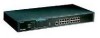
Module Indicators
 |
UPC - 790069213885
View all D-Link DFE-2616IX manuals
Add to My Manuals
Save this manual to your list of manuals |
Page 29 highlights
♦ Segment Utilization % (10Mbps and 100Mbps) The utilization bar graphs provide a quick reference on the current traffic load relative to the total available 10Mbps or 100Mbps network bandwidth. The graphs display a measure of the percentage of bandwidth in use on the respective network segment. All data packets are counted, whether valid or not. ♦ Hub ID Indicator The Hub ID readout shows the ID (group) number of the hub within the hub stack. The first time a hub is powered on within a hub stack, the master hub in the stack assigns that hub an available ID number which is then added to each hub factory serial number (encoded on an EEPROM memory chip). The hub ID is then permanently assigned. In an unmanaged stack (all slave models), all IDs will read "0" and no permanent ID assignment is made. In a stack with a master (intelligent) model, the master hub will detect the other hubs in the stack and automatically assign ID numbers which are then permanently saved by each hub. Module Indicators The two module indicators, SLOT1 and SLOT2, indicate a good link to a module installed in the respective slot. For the DFE-260S switch module the indicator will come on when the module is installed. For the DFE-260FX and DFE-260TX modules, the slot link indicator should light whenever the module is installed and there is a valid link. Understanding Indicators 17
-
 1
1 -
2
-
3
-
4
-
5
-
6
-
7
-
8
-
9
-
10
-
11
-
12
-
13
-
14
-
15
-
16
-
17
-
18
-
19
-
20
-
21
-
22
-
23
-
 24
24 -
 25
25 -
 26
26 -
 27
27 -
 28
28 -
 29
29 -
 30
30 -
 31
31 -
 32
32 -
 33
33 -
 34
34 -
35
-
36
-
37
-
38
-
39
-
40
-
41
-
42
-
43
-
44
-
45
-
46
-
47
-
48
-
49
-
50
-
51
-
52
-
53
-
54
-
55
-
56
-
57
-
58
-
59
-
60
-
61
-
62
-
63
-
64
-
65
-
66
-
67
-
68
-
69
-
70
-
71
-
72
-
73
-
74
-
75
-
76
-
77
-
78
-
79
-
80
-
81
-
82
-
83
-
84
-
85
-
86
-
87
-
88
-
89
-
90
-
91
-
92
-
93
-
94
-
95
-
96
-
97
-
98
-
99
-
100
-
101
-
102
-
103
-
104
-
105
-
106
-
107
-
108
-
109
-
110
-
111
-
112
-
113
-
114
-
115
-
116
-
117
-
118
-
119
-
120
-
121
-
122
-
123
-
124
-
125
-
126
-
127
-
128
-
129
-
130
-
131
-
132
-
133
-
134
-
135
-
136
-
137
-
138
-
139
-
140
-
141
-
142
-
143
-
144
-
145
-
146
-
147
 |
 |
