D-Link DGS-3427 Product Manual - Page 194
MST Configuration Identification, MST Configuration Identification window
 |
UPC - 790069283161
View all D-Link DGS-3427 manuals
Add to My Manuals
Save this manual to your list of manuals |
Page 194 highlights
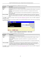
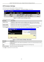
xStack® DGS-3400 Series Layer 2 Gigabit Ethernet Managed Switch Forward Delay (4-30 sec) Max Hops (1-40) TX Hold Count (1-10) Forwarding BPDU Loopback Detection LBD Recover Time NNI BPDU Address The Forward Delay can be from 4 to 30 seconds. Any port on the Switch spends this time in the listening state while moving from the blocking state to the forwarding state. Used to set the number of hops between devices in a spanning tree region before the BPDU (bridge protocol data unit) packet sent by the Switch will be discarded. Each switch on the hop count will reduce the hop count by one until the value reaches zero. The Switch will then discard the BPDU packet and the information held for the port will age out. The user may set a hop count from 1 to 40. The default is 20. If the Max Hops is less than 6, the Max Hops is 6. Used to set the maximum number of Hello packets transmitted per interval. The count can be specified from 1 to 10. The default is 6. This field can be Enabled or Disabled. When Enabled, it allows the forwarding of STP BPDU packets from other network devices. The default is Disabled. When enabled, the Switch will temporarily block STP switch-wide when a BPDU packet has looped back. If the Switch detects its own BPDU packet coming back, it signifies a loop on the network - STP is automatically blocked and an alert is sent to the administrator. The default is Enabled. Time allowed (in seconds) for recovery when an STP Loopback is detected. After the timer has expired the Switch checks for an STP loopback, if no loopback detected, STP is resumed. Entering 0 will disable LBD recovery. This field is used to configure the NNI port address. dot1d - Specifies STP's BPDU MAC address of NNI port using the definition of 802.1d. dot1ad - Specifies STP's PDU MAC address of NNI port using the definition of 802.1ad. Click Apply to implement the changes. MST Configuration Identification The following windows allow the user to configure a MSTI instance on the Switch. These settings will uniquely identify a multiple spanning tree instance set on the Switch. The Switch initially possesses one CIST or Common Internal Spanning Tree of which the user may modify the parameters for but cannot change the MSTI ID for, and cannot be deleted. To view this window, click L2 Features > Spanning Tree > MST Configuration Identification, as shown below. Figure 3 - 48 MST Configuration Identification window 185
-
 1
1 -
2
-
3
-
4
-
5
-
6
-
7
-
8
-
9
-
10
-
11
-
12
-
13
-
14
-
15
-
16
-
17
-
18
-
19
-
20
-
21
-
22
-
23
-
24
-
25
-
26
-
27
-
28
-
29
-
30
-
31
-
32
-
33
-
34
-
35
-
36
-
37
-
38
-
39
-
40
-
41
-
42
-
43
-
44
-
45
-
46
-
47
-
48
-
49
-
50
-
51
-
52
-
53
-
54
-
55
-
56
-
57
-
58
-
59
-
60
-
61
-
62
-
63
-
64
-
65
-
66
-
67
-
68
-
69
-
70
-
71
-
72
-
73
-
74
-
75
-
76
-
77
-
78
-
79
-
80
-
81
-
82
-
83
-
84
-
85
-
86
-
87
-
88
-
89
-
90
-
91
-
92
-
93
-
94
-
95
-
96
-
97
-
98
-
99
-
100
-
101
-
102
-
103
-
104
-
105
-
106
-
107
-
108
-
109
-
110
-
111
-
112
-
113
-
114
-
115
-
116
-
117
-
118
-
119
-
120
-
121
-
122
-
123
-
124
-
125
-
126
-
127
-
128
-
129
-
130
-
131
-
132
-
133
-
134
-
135
-
136
-
137
-
138
-
139
-
140
-
141
-
142
-
143
-
144
-
145
-
146
-
147
-
148
-
149
-
150
-
151
-
152
-
153
-
154
-
155
-
156
-
157
-
158
-
159
-
160
-
161
-
162
-
163
-
164
-
165
-
166
-
167
-
168
-
169
-
170
-
171
-
172
-
173
-
174
-
175
-
176
-
177
-
178
-
179
-
180
-
181
-
182
-
183
-
184
-
185
-
186
-
187
-
188
-
 189
189 -
 190
190 -
 191
191 -
 192
192 -
 193
193 -
 194
194 -
 195
195 -
 196
196 -
 197
197 -
 198
198 -
 199
199 -
200
-
201
-
202
-
203
-
204
-
205
-
206
-
207
-
208
-
209
-
210
-
211
-
212
-
213
-
214
-
215
-
216
-
217
-
218
-
219
-
220
-
221
-
222
-
223
-
224
-
225
-
226
-
227
-
228
-
229
-
230
-
231
-
232
-
233
-
234
-
235
-
236
-
237
-
238
-
239
-
240
-
241
-
242
-
243
-
244
-
245
-
246
-
247
-
248
-
249
-
250
-
251
-
252
-
253
-
254
-
255
-
256
-
257
-
258
-
259
-
260
-
261
-
262
-
263
-
264
-
265
-
266
-
267
-
268
-
269
-
270
-
271
-
272
-
273
-
274
-
275
-
276
-
277
-
278
-
279
-
280
-
281
-
282
-
283
-
284
-
285
-
286
-
287
-
288
-
289
-
290
-
291
-
292
-
293
-
294
-
295
-
296
-
297
-
298
-
299
-
300
-
301
-
302
-
303
-
304
-
305
-
306
-
307
-
308
-
309
-
310
-
311
-
312
-
313
-
314
-
315
-
316
-
317
-
318
-
319
-
320
-
321
-
322
-
323
-
324
-
325
-
326
-
327
-
328
-
329
-
330
-
331
-
332
-
333
-
334
-
335
-
336
-
337
-
338
-
339
-
340
-
341
-
342
-
343
-
344
-
345
-
346
-
347
-
348
-
349
-
350
-
351
-
352
-
353
-
354
-
355
-
356
-
357
-
358
-
359
-
360
-
361
-
362
-
363
-
364
-
365
-
366
-
367
-
368
-
369
-
370
-
371
-
372
-
373
-
374
-
375
-
376
-
377
-
378
-
379
-
380
-
381
-
382
-
383
-
384
-
385
-
386
-
387
-
388
-
389
-
390
-
391
-
392
-
393
-
394
-
395
-
396
-
397
-
398
-
399
-
400
-
401
-
402
-
403
-
404
-
405
-
406
-
407
-
408
-
409
-
410
-
411
-
412
-
413
-
414
-
415
-
416
-
417
-
418
-
419
-
420
-
421
-
422
-
423
-
424
 |
 |
