D-Link DGS-3427 Product Manual - Page 262
Priority 0-7, Group ID 1-4, Offset, RX Rate 1-156249, Time Range, Time Range Settings, Counter,
 |
UPC - 790069283161
View all D-Link DGS-3427 manuals
Add to My Manuals
Save this manual to your list of manuals |
Page 262 highlights
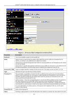
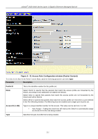
xStack® DGS-3400 Series Layer 2 Gigabit Ethernet Managed Switch Priority (0-7) Group ID (1-4) Offset This parameter is specified to re-write the 802.1p default priority previously set in the Switch, which is used to determine the CoS queue to which packets are forwarded to. Once this field is specified, packets accepted by the Switch that match this priority are forwarded to the CoS queue specified previously by the user. Replace priority with − Tick the corresponding check box if you want to re-write the 802.1p default priority of a packet to the value entered in the Priority field, which meets the criteria specified previously in this command, before forwarding it on to the specified CoS queue. Otherwise, a packet will have its incoming 802.1p user priority re-written to its original value before being forwarded by the Switch. For more information on priority queues, CoS queues and mapping for 802.1p, see the QoS section of this manual. Enter a mirror group ID. This field will instruct the Switch to mask the packet header beginning with the offset value specified: • Chunk 1 - Enter a value in hex form to mask the packet from the beginning of the packet to the first chunk. • Chunk 2 - Enter a value in hex form to mask the packet from the end of the first chunk to the end of the second chunk. • Chunk 3 - Enter a value in hex form to mask the packet from the end of the second chunk to the end of the third chunk. • Chunk 4 - Enter a value in hex form to mask the packet from the end of the third chunk to the end of the fourth chunk. Port The Access Rule may be configured on a per-port basis by entering the port number of the switch in the switch stack into this field. When a range of ports is to be configured, the Auto Assign check box MUST be ticked in the Access ID field of this window. If not, the user will be presented with an error message and the access rule will not be configured. The beginning and end of the port list range are separated by a dash. Entering all will denote all ports on the Switch. RX Rate (1-156249) Use this to limit RX bandwidth for the profile being configured. This rate is implemented using the following equation: 1 value = 64kbit/sec. (ex. If the user selects an RX rate of 10 then the ingress rate is 640kbit/sec.) The user many select a value between 1 and 156249 or No Limit. The default setting is No Limit. Time Range Tick the check box and enter the name of the Time Range settings that has been previously configured in the Time Range Settings window. This will set specific times when this access rule will be implemented on the Switch. Counter Tick the check box and use the pull-down menu to employ the Counter that will count the packets identified with this rule. Users must note that if the Counter is employed in the ACL Flow Meter function, the Counter will automatically be disabled here, regardless of this setting. Replace DSCP (063) Select this option to instruct the Switch to replace the DSCP value (in a packet that meets the selected criteria) with the value entered in the adjacent field. Click Apply to implement the changes. To view the settings of a previously correctly configured rule, click View in the Access Rule Table window to view the following window: 253
-
 1
1 -
2
-
3
-
4
-
5
-
6
-
7
-
8
-
9
-
10
-
11
-
12
-
13
-
14
-
15
-
16
-
17
-
18
-
19
-
20
-
21
-
22
-
23
-
24
-
25
-
26
-
27
-
28
-
29
-
30
-
31
-
32
-
33
-
34
-
35
-
36
-
37
-
38
-
39
-
40
-
41
-
42
-
43
-
44
-
45
-
46
-
47
-
48
-
49
-
50
-
51
-
52
-
53
-
54
-
55
-
56
-
57
-
58
-
59
-
60
-
61
-
62
-
63
-
64
-
65
-
66
-
67
-
68
-
69
-
70
-
71
-
72
-
73
-
74
-
75
-
76
-
77
-
78
-
79
-
80
-
81
-
82
-
83
-
84
-
85
-
86
-
87
-
88
-
89
-
90
-
91
-
92
-
93
-
94
-
95
-
96
-
97
-
98
-
99
-
100
-
101
-
102
-
103
-
104
-
105
-
106
-
107
-
108
-
109
-
110
-
111
-
112
-
113
-
114
-
115
-
116
-
117
-
118
-
119
-
120
-
121
-
122
-
123
-
124
-
125
-
126
-
127
-
128
-
129
-
130
-
131
-
132
-
133
-
134
-
135
-
136
-
137
-
138
-
139
-
140
-
141
-
142
-
143
-
144
-
145
-
146
-
147
-
148
-
149
-
150
-
151
-
152
-
153
-
154
-
155
-
156
-
157
-
158
-
159
-
160
-
161
-
162
-
163
-
164
-
165
-
166
-
167
-
168
-
169
-
170
-
171
-
172
-
173
-
174
-
175
-
176
-
177
-
178
-
179
-
180
-
181
-
182
-
183
-
184
-
185
-
186
-
187
-
188
-
189
-
190
-
191
-
192
-
193
-
194
-
195
-
196
-
197
-
198
-
199
-
200
-
201
-
202
-
203
-
204
-
205
-
206
-
207
-
208
-
209
-
210
-
211
-
212
-
213
-
214
-
215
-
216
-
217
-
218
-
219
-
220
-
221
-
222
-
223
-
224
-
225
-
226
-
227
-
228
-
229
-
230
-
231
-
232
-
233
-
234
-
235
-
236
-
237
-
238
-
239
-
240
-
241
-
242
-
243
-
244
-
245
-
246
-
247
-
248
-
249
-
250
-
251
-
252
-
253
-
254
-
255
-
256
-
 257
257 -
 258
258 -
 259
259 -
 260
260 -
 261
261 -
 262
262 -
 263
263 -
 264
264 -
 265
265 -
 266
266 -
 267
267 -
268
-
269
-
270
-
271
-
272
-
273
-
274
-
275
-
276
-
277
-
278
-
279
-
280
-
281
-
282
-
283
-
284
-
285
-
286
-
287
-
288
-
289
-
290
-
291
-
292
-
293
-
294
-
295
-
296
-
297
-
298
-
299
-
300
-
301
-
302
-
303
-
304
-
305
-
306
-
307
-
308
-
309
-
310
-
311
-
312
-
313
-
314
-
315
-
316
-
317
-
318
-
319
-
320
-
321
-
322
-
323
-
324
-
325
-
326
-
327
-
328
-
329
-
330
-
331
-
332
-
333
-
334
-
335
-
336
-
337
-
338
-
339
-
340
-
341
-
342
-
343
-
344
-
345
-
346
-
347
-
348
-
349
-
350
-
351
-
352
-
353
-
354
-
355
-
356
-
357
-
358
-
359
-
360
-
361
-
362
-
363
-
364
-
365
-
366
-
367
-
368
-
369
-
370
-
371
-
372
-
373
-
374
-
375
-
376
-
377
-
378
-
379
-
380
-
381
-
382
-
383
-
384
-
385
-
386
-
387
-
388
-
389
-
390
-
391
-
392
-
393
-
394
-
395
-
396
-
397
-
398
-
399
-
400
-
401
-
402
-
403
-
404
-
405
-
406
-
407
-
408
-
409
-
410
-
411
-
412
-
413
-
414
-
415
-
416
-
417
-
418
-
419
-
420
-
421
-
422
-
423
-
424
 |
 |
