Dell Force10 E600i E600 TeraScale Installation Guide
Dell Force10 E600i Manual
 |
View all Dell Force10 E600i manuals
Add to My Manuals
Save this manual to your list of manuals |
Dell Force10 E600i manual content summary:
- Dell Force10 E600i | E600 TeraScale Installation Guide - Page 1
E600i TeraScale Installation Guide - Dell Force10 E600i | E600 TeraScale Installation Guide - Page 2
damage to hardware or loss of data if instructions are not followed. WARNING: A WARNING indicates a potential for property damage, personal injury, or death. Information in this publication is subject to change without notice. © 2011 Dell Force10. All rights reserved. Reproduction of these materials - Dell Force10 E600i | E600 TeraScale Installation Guide - Page 3
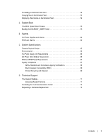
Power Requirements 10 2500W AC Power Requirements 10 DC Power Requirements 10 Storage Requirements 10 3 The E600i System Operating Overview 11 E600i System Installation Process 13 4 Installing the Chassis Unpacking the E600i System 15 Installing the Equipment Rack Shelf Bar 15 Standard Front - Dell Force10 E600i | E600 TeraScale Installation Guide - Page 4
www.dell.com | support.dell.com 7 Installing RPMs, Line Cards, and SFMs Unpacking 29 Cable and Adapter Pin Assignments 38 Accessing the Console with a DB-9 Adapter 39 Accessing the Console with a DB-25 Adapter 39 Accessing the Auxiliary Port by Modem 40 Accessing the 10/100 Ethernet Management - Dell Force10 E600i | E600 TeraScale Installation Guide - Page 5
Stored on the External Flash 52 A System Boot The E600i System Boot Process 55 Booting from the BOOT_USER Prompt 62 SFMs and Alarms 62 C System Specifications Chassis Physical Design 65 Environmental 66 AC Power Supply Technical Support The iSupport Website 71 Accessing iSupport Services 71 - Dell Force10 E600i | E600 TeraScale Installation Guide - Page 6
www.dell.com | support.dell.com 6 | Contents - Dell Force10 E600i | E600 TeraScale Installation Guide - Page 7
, step-by-step procedures to rack mount the Dell Force10 E600i chassis, as well as instructions to install fan tray, power modules, route processor modules (RPMs), switch fabric modules (SFMs), and line cards. This guide also includes instructions to remove and install field-replaceable parts. The - Dell Force10 E600i | E600 TeraScale Installation Guide - Page 8
www.dell.com | support.dell.com CAUTION: Wear grounding wrist straps when handling this equipment to on page 69. Related Publications For more information about the E600i system, refer to the following documents: • FTOS Configuration Guide • FTOS Command Reference • Release Notes for the E-Series - Dell Force10 E600i | E600 TeraScale Installation Guide - Page 9
at the top rear. For proper ventilation, position the chassis in an equipment rack or cabinet so that the minimum air flow is 750 cubic feet per minute (CFM), this requires a minimum of 3 inches between the doors and the cable management system when the cabinet front doors are closed, and a minimum - Dell Force10 E600i | E600 TeraScale Installation Guide - Page 10
replace all the PSUs in your system with the new versions. Contact Dell Force10 Technical Support if you have any question regarding the version of PSU used in your system. 2500W AC Power Requirements The E600i 2500W AC power supply (CAT# CC-E600i-2500W-AC2) can operate at either 100 VAC or 220 VAC - Dell Force10 E600i | E600 TeraScale Installation Guide - Page 11
reliability. Operating the E600i system with two RPMs enables automatic fail-over redundancy. Line cards perform all data forwarding operations. Each line card has Dell Force10 proprietary ASICs; the flexible packet classification (FPC) ASIC and the Buffer and Traffic Manager (BTM) ASIC. The - Dell Force10 E600i | E600 TeraScale Installation Guide - Page 12
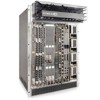
www.dell.com | support.dell.com Figure 3-1. E600i Chassis Front View with AC Power Supplies RPMs ESD Connector Line Cards Air Filter SFM3 Figure 3-2. E600i Chassis Rear View Fan Tray Status LED AC Power Supplies Fan Tray Grounding Holes 12 | The E600i System Grounding Holes - Dell Force10 E600i | E600 TeraScale Installation Guide - Page 13
DC PEMs 2 4 1 2 Cable management system 0 1 Cable management system cover 0 1 *Fan tray is field replaceable, but must be replaced within 1 minute of removing it. Field-Replaceable N Y Y Y Y Y Y Y Y Y E600i System Installation Process To install the E600i system, Dell Force10 recommends - Dell Force10 E600i | E600 TeraScale Installation Guide - Page 14
14 | The E600i System www.dell.com | support.dell.com - Dell Force10 E600i | E600 TeraScale Installation Guide - Page 15
This chapter provides instructions to rack mount your E600i system into a standard 19-inch or 23-inch equipment rack. It contains the following sections: • Unpacking the E600i System • Installing the Equipment Rack Shelf Bar • Standard Front Chassis Rack Mounting • Installing the Chassis into an - Dell Force10 E600i | E600 TeraScale Installation Guide - Page 16
dell.com | support.dell.com Figure 4-1. Installing the Equipment Rack Shelf Bar UP UP F To install a equipment rack shelf bar: Step Task 1 Determine the chassis Front Chassis Rack Mounting Install the E600i system after you secure the equipment rack shelf bar. Load the chassis into the - Dell Force10 E600i | E600 TeraScale Installation Guide - Page 17
Install the E600i system after you secure the rack shelf bar. Load the chassis into the lower half of an empty rack to avoid a top-heavy rack. (Figure 4-2). Make sure the cabinet is positioned with adequate space in the front, rear, and sides of the unit for proper ventilation, access to cables, and - Dell Force10 E600i | E600 TeraScale Installation Guide - Page 18
18 | Installing the Chassis www.dell.com | support.dell.com - Dell Force10 E600i | E600 TeraScale Installation Guide - Page 19
when components are mishandled. Always wear an ESD-preventative wrist or foot-heal ground strap when handling chassis components. After you remove the original packaging, place chassis components on an antistatic surface. Figure 5-1. The Fan Tray Status LED FN0076A Ensure that the power switches - Dell Force10 E600i | E600 TeraScale Installation Guide - Page 20
www.dell.com | support.dell.com Figure 5-2. Inserting Fan Tray into Fan Slot FN00080A Fan Speed Fan speed is driven by temperatures measured at the sensor in the fan tray - Dell Force10 E600i | E600 TeraScale Installation Guide - Page 21
6 Power Supply This chapter provides instructions to install AC Power Supply Units (PSUs) and DC Power Entry Modules (PEMs): • AC Power Supply Units • DC Power Entry Modules E-Series systems may contain only one type of power module-AC or DC. The E600i requires a minimum of one DC Power Entry - Dell Force10 E600i | E600 TeraScale Installation Guide - Page 22
dell.com | support.dell. removing and replacing a power supply unit, determine if the E600i is in full redundancy or non-redundant mode. Operating in mix power supplies. Installing a 2500W-AC2 power supply into a chassis with 2500W-AC power supplies already installed may result in unpredictable - Dell Force10 E600i | E600 TeraScale Installation Guide - Page 23
appropriately sized plug that complies with your local electrical codes. Conductor size must also conform to your local electrical codes. The following are Dell Force10 supplied plug types. • EU: CEE 7/7 • UK:CEE7/7, BS 1363 • SWZ: CEE7/7, 309 • JAP: NEMA 5-20 • JAP 220: NEMA 6-20, L6-20 • US: C14 - Dell Force10 E600i | E600 TeraScale Installation Guide - Page 24
www.dell.com | support.dell.com Step Task 5 Plug the AC power cord into an AC outlet. 6 Toggle the power supply switch to the ON position, and verify that Status - Dell Force10 E600i | E600 TeraScale Installation Guide - Page 25
, but two are recommended for redundancy. Connect the E600 PEMs to the appropriate branch circuit protection as defined cables are: • rated for at least 80A service to allow for a fully loaded E600i system at low input voltage per your local electrical codes • limit voltage drop across the cable - Dell Force10 E600i | E600 TeraScale Installation Guide - Page 26
.sircchuailtter DsCooAunrUcoeTt pIcOlouNngn-ienUctwnioihtnim.leRaeeynmheoarvgveeizaemldlo.srueptphlyancoonnneecptoiownesr CC-E600-CVR-PEM 4 Slide the backplane connector end of the PEM into Power Supply Slot 1 or 3. Secure the PEM to the chassis by tighten the two locking screws. 5 Secure - Dell Force10 E600i | E600 TeraScale Installation Guide - Page 27
Current Protector (located on the PEM front panel) to the OFF position. 4 Loosen the PEM safety cover retaining screw, and remove the cover. 5 Disconnect power cables attached to the PEM. 6 Slide the PEM out of the slot. 7 If you are not replacing the PEM, place a power supply blank in the empty - Dell Force10 E600i | E600 TeraScale Installation Guide - Page 28
28 | Power Supply www.dell.com | support.dell.com - Dell Force10 E600i | E600 TeraScale Installation Guide - Page 29
, Line Cards, and SFMs This chapter provides instructions to install cards into the E600i chassis and includes the following sections: • Unpacking • supply power to your E600i system until the fan tray, RPMs, SFMs, line cards, and any required blanks are installed. Dell Force10 recommends that you - Dell Force10 E600i | E600 TeraScale Installation Guide - Page 30
dell.com | support.dell Force10 Networks custom-built ASICs, which enable line-rate forwarding. Line Card Port Numbering There are seven line card slots available in the E600i chassis with the guide and gently slide it into the slot until you feel the connectors engage with the chassis backplane. NOTE - Dell Force10 E600i | E600 TeraScale Installation Guide - Page 31
E600i FN00079A To install line cards and RPMs: Step 1 2 3 4 5 Task Remove the line card from its box and carefully remove the line card from the anti-static packaging. Align the RPM with the guide and gently slide it into the slot until you feel the connectors engage with the chassis backplane - Dell Force10 E600i | E600 TeraScale Installation Guide - Page 32
.dell.com | support.dell. RPMs control the routing and switching functions for the entire E600i system. The E600i operates with a minimum of one RPM module. You the primary RPM was performing. Table 7-1. RPM LEDs Section Management Label 10/100 Ethernet Alarms Major Minor ACO/LT Description - Dell Force10 E600i | E600 TeraScale Installation Guide - Page 33
(SFMs) A minimum of four SFMs are required in order for the E600i system to operate properly. There is an additional slot available for a . 2 Align the SFM with the guide and gently slide it into the slot until you feel the connectors engage with the chassis backplane. NOTE: Hold the SFM by - Dell Force10 E600i | E600 TeraScale Installation Guide - Page 34
www.dell.com | support.dell.com FN0008 Figure 7-2. Installing SFMs Load SFMs from right to left 34 | Installing RPMs, Line Cards, and SFMs - Dell Force10 E600i | E600 TeraScale Installation Guide - Page 35
SFM Front Panel and LEDs Table 7-2 defines the SFM front panel and LED displays. Table 7-2. SFM Front Panel and LED Descriptions CC-E-SFM3 Active LED Active Status Description Green: active and passing traffic Unlit: in standby mode Flashing Green: booting Green: operational Flashing Amber: - Dell Force10 E600i | E600 TeraScale Installation Guide - Page 36
www.dell.com | support.dell.com 36 | Installing RPMs, Line Cards, and SFMs - Dell Force10 E600i | E600 TeraScale Installation Guide - Page 37
RPM Ports • Cable and Adapter Pin Assignments • Accessing the 10/100 Ethernet Management Port RPM Ports supported on this port. • Auxiliary. A UART port with an RJ-45 jack, allows modem access to the E600i system from a remote location. • 10/100 Ethernet. A 10/100 Ethernet port is the Management - Dell Force10 E600i | E600 TeraScale Installation Guide - Page 38
www.dell.com | support.dell.com Cable and Adapter Pin Assignments Use the E600i Console port on the RPM to connect to a terminal port, PC serial port, or a terminal server to configure and monitor your system. Use the E600i Auxiliary port on the RPM to connect to a modem. Both the Console and - Dell Force10 E600i | E600 TeraScale Installation Guide - Page 39
You can connect to the console using a RJ-45 to RJ-45 rollover cable and a RJ-45 to a DB-25 female DTE adapter. Table 8-4 lists the pin assignments. Table 8-4. Pin Assignments Between E600i Console and DB-25 Adapter E600i Console Port Signal RTS DTR TxD GND GND RxD DSR CTS RJ-45 to - Dell Force10 E600i | E600 TeraScale Installation Guide - Page 40
.dell.com | support.dell.com Accessing the Auxiliary Port by Modem You can access the auxiliary port using a dial-up modem using a RJ-45 to RJ-45 rollover cable Management Port Configure the 10/100 Ethernet management port, labeled 10/100 Ethernet on the primary RPM card in order to obtain network - Dell Force10 E600i | E600 TeraScale Installation Guide - Page 41
instructions for powering up your E600i system once you have installed all the chassis components and made your power and network supply power to the chassis. Before you supply power to your chassis, Dell Force10 recommends that you re-inspect your equipment rack and chassis. Verify that: - Dell Force10 E600i | E600 TeraScale Installation Guide - Page 42
www.dell.com | support.dell.com Step Task 4 The fan tray LED should be green (online). Verify that air is flowing through the chassis. If the fans are not operating properly or air is not flowing through the chassis, power off the chassis at the power module. Ensure that the fan is properly - Dell Force10 E600i | E600 TeraScale Installation Guide - Page 43
and Replacing Parts This chapter provides instructions for removing and replacing E600i components. It covers the following E600i with a #2 Phillips screwdriver. 3 Grip both handles and pull the fan tray halfway out of the chassis. 4 Grip the sides of the fan tray and pull it from chassis. - Dell Force10 E600i | E600 TeraScale Installation Guide - Page 44
www.dell.com | support.dell.com FN0076A Figure 10-1. Fan Tray Removing and Replacing Power Modules The E600i supports a minimum of one DC PEM or three 100 VAC Power Supplies (two for 200 VAC). You must have one type of power module in the chassis; you cannot install a mixture of power supply - Dell Force10 E600i | E600 TeraScale Installation Guide - Page 45
. If you are not replacing the power supply, replace the empty slot with a power supply blank cover. Replacing DC PEMs If you are operating your E600i chassis with redundant DC PEMs, you can install, remove, or replace a DC PEM without affecting system operation. If you are operating your - Dell Force10 E600i | E600 TeraScale Installation Guide - Page 46
dell.com | support.dell.com Figure 10-3. DC PEM Label Voltage 'good' LED Status LED Handle Studs 48V in Status Over Current Protector CC-E600 position. 3 Loosen the retaining screw and remove PEM safety cover. 4 Disconnect power cables attached to the PEM. 5 Slide the PEM out of the slot. 6 If - Dell Force10 E600i | E600 TeraScale Installation Guide - Page 47
cards, and SFMs are hot-swappable. The E600i system generates major alarm events for module failures line cards: Step Task 1 Unplug the network interface cables connected to the line card or RPM. guide and gently slide the card into the slot until you feel the connectors engage with the chassis - Dell Force10 E600i | E600 TeraScale Installation Guide - Page 48
www.dell.com | support.dell.com Step Task (continued) 4 Align the new SFM with the guide and gently slide the card into the slot until you feel the connectors engage with the chassis backplane. NOTE: Hold the SFM by the edges. Avoid touching the printed circuit board and connector pins. Extend - Dell Force10 E600i | E600 TeraScale Installation Guide - Page 49
remove and replace the air filter: Step Task 1 Pull the air filter straight out of the chassis to remove. 2 Rotate the replacement filter so that the side with the label "This Side Up" is facing upward. Guide the filter firmly into the slot until it stops. Removing and Replacing Parts | 49 - Dell Force10 E600i | E600 TeraScale Installation Guide - Page 50
50 | Removing and Replacing Parts www.dell.com | support.dell.com - Dell Force10 E600i | E600 TeraScale Installation Guide - Page 51
card to copy the image and configuration files for storage and backup purposes. For complex configurations, use the copies for other E600i systems in your network. Configure your boot execution process to use the images stored on a flash card as the primary (active), secondary (standby), or default - Dell Force10 E600i | E600 TeraScale Installation Guide - Page 52
www.dell.com | support.dell.com Formatting an External Flash Card New external flash cards must be formatted in the E600i before use. Flash cards used on systems other than the E600i as well as cards formatted on PCs must be reformatted in the E600i flash slot before they can be used. Similar to - Dell Force10 E600i | E600 TeraScale Installation Guide - Page 53
Figure 11-1. dir Command Example Force10#dir slot0: Directory of slot0: 1 -rwx 6478482 Sep 7 101 16:54:34 E1200.BIN FTOS supports up to a 40-character file name length, up to a 180-character local file path length, and up to a 256-character remote file path length. Refer - Dell Force10 E600i | E600 TeraScale Installation Guide - Page 54
54 | Using a Flash Memory Card www.dell.com | support.dell.com - Dell Force10 E600i | E600 TeraScale Installation Guide - Page 55
instructions to boot the E600i system from the BOOT_USER prompt. The E600i System Boot Process When you supply power to the E600i Force10>. The RPM cards in the E600i CLI mode. NOTE: The E600i system supports up to a 40- problems. This mode allows you to modify the parameters necessary to manage - Dell Force10 E600i | E600 TeraScale Installation Guide - Page 56
To configure the chassis from the BOOT_USER prompt: 1 help or ? • The BOOT_USER # prompt BOOT_USER # show bootflash GENERAL BOOTFLASH INFO Bootflash Partition A: Force10 Networks System Boot Copyright 1999-2001 Force10 Networks, Inc. ROM Header Version 1.0 Official CP_IMG_BOOT, BSP Release - Dell Force10 E600i | E600 TeraScale Installation Guide - Page 57
system boot configuration parameters. BOOT_USER # show bootvar PRIMARY OPERATING SYSTEM BOOT PARAMETERS: boot device : flash file name : /E600i-x.bin SECONDARY OPERATING SYSTEM BOOT PARAMETERS: 5 boot change {primary | If your configuration displays no pre-configured operating system - Dell Force10 E600i | E600 TeraScale Installation Guide - Page 58
www.dell.com | support.dell.com 6 interface management port • (OPTIONAL) Use these commands to set the speed and duplex settings for the config 100m Management interface.The default setting is full-duplex and auto-negotiation. interface management port • Use the interface management port config - Dell Force10 E600i | E600 TeraScale Installation Guide - Page 59
1787 FEB-23-2006 22:42:46 name -------E600i-.bin E600i-3.bin E600i-2.bin E600i-3.1.bin startup-config BOOT_USER # 10 reload 11 Force10> Reload software. The autoboot program initializes and displays details, and to the FTOS Configuration Guide for configuration procedures. System Boot | 59 - Dell Force10 E600i | E600 TeraScale Installation Guide - Page 60
60 | System Boot www.dell.com | support.dell.com - Dell Force10 E600i | E600 TeraScale Installation Guide - Page 61
, LEDs, and audible alarms. If you configure the SNMP command (snmp-server enable traps envmon), the FTOS also sends an SNMP trap. In the E600i system, alarms are logged for each occurrence, but the system may not send an event log for multiple occurrences. For example, whenever a module exceeds - Dell Force10 E600i | E600 TeraScale Installation Guide - Page 62
www.dell.com | support.dell.com Table B-1. Alarm Events and Reporting Module Alarm Event (redundant) SFM is removed or fails. At boot time, if five SFMs are present and functioning, the E600i system issues no alarms. However, if one SFM fails or is removed, the system send a minor alarm stating - Dell Force10 E600i | E600 TeraScale Installation Guide - Page 63
At boot time, if four SFMs are present and functioning, the E600i system issues no alarms. The system issues no alarms if a fifth SFM is added to the system; however, if the number of functioning SFMs changes - Dell Force10 E600i | E600 TeraScale Installation Guide - Page 64
64 | Alarms www.dell.com | support.dell.com - Dell Force10 E600i | E600 TeraScale Installation Guide - Page 65
Physical Design Parameter Specifications Height 28 inches (71.1 cm) Width 17.4 inches (44.2 cm) Depth (without cable management system) 21.5 inches (54.6 cm) Chassis weight with factory-installed components (backplane and air filter) 81 pounds (36.7 kg) Weight fully loaded (backplane - Dell Force10 E600i | E600 TeraScale Installation Guide - Page 66
www.dell.com | support.dell.com Environmental Parameter Operating: Temperature Maximum altitude Relative humidity Non-operating: Temperature Maximum altitude Relative humidity Specifications 32° to 104°F (0° to 40°C) No performance degradation - Dell Force10 E600i | E600 TeraScale Installation Guide - Page 67
) 150W (510 BTU/hour) Agency Compliance The E600i is designed to comply with the following safety and not installed and used in accordance to the instructions, it may cause harmful interference to radio cables and connectors must be used in order to meet FCC emission limits. Dell Force10 is - Dell Force10 E600i | E600 TeraScale Installation Guide - Page 68
www.dell.com | support.dell.com Japan: VCCI Compliance for Class A Equipment This is Class A product arise. When such trouble occurs, the user may be required to take corrective actions. WARNING: AC Power cords are for use with Dell Force10 equipment only. Do not use Dell Force10 AC power cords with - Dell Force10 E600i | E600 TeraScale Installation Guide - Page 69
-Part 1: Equipment Classification Requirements and User's Guide • EN 60825-2 Safety of Laser Products-Part , Subpart B, Class A Immunity • EN 300 386 V1.3.3: 2005 EMC for Network Equipment • EN 55024 1998 + A1: 2001 + A2: 2003 • EN Dell Force10 offers a variety of product return programs and services - Dell Force10 E600i | E600 TeraScale Installation Guide - Page 70
Dell Force10 product recycling offerings, see the WEEE Recycling instructions on iSupport at: https://www.force10networks.com/CSPortal20/Support/WEEEandRecycling.pdf. For more information, contact the Dell Force10 33. Best Management Practices for Perchlorate Materials. 70 | System Specifications - Dell Force10 E600i | E600 TeraScale Installation Guide - Page 71
: Case management • Software Center: Software downloads, bug fixes, and bug tracking tool • Documents: User documentation, FAQs, field notices, technical tips, and white papers • Support Programs: Information on the suite of Dell Force10 support and professional support services. The Support Guide - Dell Force10 E600i | E600 TeraScale Installation Guide - Page 72
in the output of show tech-support.) • Console captures showing the error messages • Console captures showing the troubleshooting steps taken • Saved messages to a syslog server, if one is used Managing Your Case Log in to iSupport, and select the Service Request tab to view all open cases - Dell Force10 E600i | E600 TeraScale Installation Guide - Page 73
support case. Open a support case by: • Using the Create Service Request form on the iSupport page (see Contacting the Technical Assistance Center on page 72). • Contacting Dell Force10 tech-support.) • Console captures showing the error messages • Console captures showing the troubleshooting - Dell Force10 E600i | E600 TeraScale Installation Guide - Page 74
74 | Technical Support www.dell.com | support.dell.com - Dell Force10 E600i | E600 TeraScale Installation Guide - Page 75
- Dell Force10 E600i | E600 TeraScale Installation Guide - Page 76
Printed in the U.S.A. www.dell.com | support.dell.com
-
 1
1 -
 2
2 -
 3
3 -
 4
4 -
 5
5 -
 6
6 -
 7
7 -
8
-
9
-
10
-
11
-
12
-
13
-
14
-
15
-
16
-
17
-
18
-
19
-
20
-
21
-
22
-
23
-
24
-
25
-
26
-
27
-
28
-
29
-
30
-
31
-
32
-
33
-
34
-
35
-
36
-
37
-
38
-
39
-
40
-
41
-
42
-
43
-
44
-
45
-
46
-
47
-
48
-
49
-
50
-
51
-
52
-
53
-
54
-
55
-
56
-
57
-
58
-
59
-
60
-
61
-
62
-
63
-
64
-
65
-
66
-
67
-
68
-
69
-
70
-
71
-
72
-
73
-
74
-
75
-
76
 |
 |

E600i TeraScale
Installation Guide