Dell Force10 E600i E600 TeraScale Installation Guide - Page 30
Line Cards, Blank Panels, Preparing and Installing the RPMs and Line Cards
 |
View all Dell Force10 E600i manuals
Add to My Manuals
Save this manual to your list of manuals |
Page 30 highlights
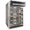
www.dell.com | support.dell.com You can hot-insert a second RPM into a running system without performance interruption or software intervention. A second RPM for redundant functionality provides uninterrupted operability if the system transitions from the active RPM to the standby RPM. The standby RPM constantly performs updates and receives the same configuration information received by the active RPM. The standby RPM also performs diagnostics on its subsystems. In the event of a switch over, the standby RPM immediately takes over and resumes the control activities that the active RPM was performing. Installing a Second RPM provides more information on the second RPM. The RPM Major and Minor alarm LEDs are controlled by software which sets the threshold levels for triggering the different stages of alarms. Line Cards Your E600i configuration requires a minimum of one line card. Line cards are hot swappable. The line card ports provide external interface functions for connections to other systems (for example, a router or switch). Each line card has an onboard CPU for line card management which updates packet forwarding information, obtains statistical information, and performs synchronization tasks with the RPM, as well as Force10 Networks custom-built ASICs, which enable line-rate forwarding. Line Card Port Numbering There are seven line card slots available in the E600i chassis. A minimum of one line card is required for operation. Line cards are installed in slots 0 through 6. Ports on line cards are numbered from the top, starting from 0. Blank Panels CAUTION: To avoid chassis over-temperature condition, install blanks for RPMs, SFMs, and line cards slots that are not in use. Always replace cards or blanks immediately. Blank panels for RPMs, SFMs, and line cards must be installed in empty slots to control airflow. If a slot is not filled for more than five minutes, the following message appears on the console: %CHMGR-2-MINORTEMP: Minor alarm: chassis temperature high (SFM temperature reaches or exceeds threshold of 65C) Blank panels are shipped with the system to ensure that all chassis slots are installed with operational modules or blanks. Preparing and Installing the RPMs and Line Cards To install line cards and RPMs: Step 1 2 3 4 Task Remove the line card from its box and carefully remove the line card from the anti-static packaging. Align the RPM with the guide and gently slide it into the slot until you feel the connectors engage with the chassis backplane. NOTE: Hold the card by the edges. Avoid touching the printed circuit board and connector pins. Extend the top and bottom card levers before you insert the card into the slot. Rotate the levers to seat the backplane connectors and line card in place. Secure card and blanks in place by tightening the top and captive screws on each card. 30 | Installing RPMs, Line Cards, and SFMs
-
 1
1 -
2
-
3
-
4
-
5
-
6
-
7
-
8
-
9
-
10
-
11
-
12
-
13
-
14
-
15
-
16
-
17
-
18
-
19
-
20
-
21
-
22
-
23
-
24
-
 25
25 -
 26
26 -
 27
27 -
 28
28 -
 29
29 -
 30
30 -
 31
31 -
 32
32 -
 33
33 -
 34
34 -
 35
35 -
36
-
37
-
38
-
39
-
40
-
41
-
42
-
43
-
44
-
45
-
46
-
47
-
48
-
49
-
50
-
51
-
52
-
53
-
54
-
55
-
56
-
57
-
58
-
59
-
60
-
61
-
62
-
63
-
64
-
65
-
66
-
67
-
68
-
69
-
70
-
71
-
72
-
73
-
74
-
75
-
76
 |
 |
