Dell Force10 E600i E600 TeraScale Installation Guide - Page 13

E600i System Installation Process, Table 3-1., E600i Hardware Component Operating Requirements Summary
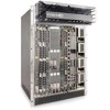
Page 13 highlights

Table 3-1. E600i Hardware Component Operating Requirements Summary Component Minimum Maximum Backplane (factory installed) 1 1 Air filter (factory installed) 1 1 Fan tray* 1 1 RPMs 1 2 Line cards 1 7 SFMs 4 5 Power Supplies: 2500 AC Power Supply OR DC PEMs 2 4 1 2 Cable management system 0 1 Cable management system cover 0 1 *Fan tray is field replaceable, but must be replaced within 1 minute of removing it. Field-Replaceable N Y Y Y Y Y Y Y Y Y E600i System Installation Process To install the E600i system, Dell Force10 recommends that you perform the installation procedures in the following order: Step 1 2 3 Task Prepare the site Unpack the chassis and components Mount the chassis 4 Install components: • Fan tray • AC Power Supply or DC PEMs (including power cables) 5 Install card components: • RPM(s) and line cards • SFMs 6 Connect network cable 7 Supply power to the chassis Section Site Preparation Unpacking the E600i System Standard Front Chassis Rack Mounting Installing the Chassis into an Equipment Cabinet Installing the Fan Tray Power Supply Preparing and Installing the RPMs and Line Cards Installing Switch Fabric Modules (SFMs) RPM Ports and Cables Powering Up The E600i System | 13

  • 1
  • 2
  • 3
  • 4
  • 5
  • 6
  • 7
  • 8
  • 9
  • 10
  • 11
  • 12
  • 13
  • 14
  • 15
  • 16
  • 17
  • 18
  • 19
  • 20
  • 21
  • 22
  • 23
  • 24
  • 25
  • 26
  • 27
  • 28
  • 29
  • 30
  • 31
  • 32
  • 33
  • 34
  • 35
  • 36
  • 37
  • 38
  • 39
  • 40
  • 41
  • 42
  • 43
  • 44
  • 45
  • 46
  • 47
  • 48
  • 49
  • 50
  • 51
  • 52
  • 53
  • 54
  • 55
  • 56
  • 57
  • 58
  • 59
  • 60
  • 61
  • 62
  • 63
  • 64
  • 65
  • 66
  • 67
  • 68
  • 69
  • 70
  • 71
  • 72
  • 73
  • 74
  • 75
  • 76

The E600i System
|
13
E600i System Installation Process
To install the E600i system, Dell Force10 recommends that you perform the installation procedures in the
following order:
Table 3-1.
E600i Hardware Component Operating Requirements Summary
Component
Minimum
Maximum
Field-Replaceable
Backplane (factory installed)
1
1
N
Air filter (factory installed)
1
1
Y
Fan tray*
1
1
Y
RPMs
1
2
Y
Line cards
1
7
Y
SFMs
4
5
Y
Power Supplies:
2500 AC Power Supply
OR
DC PEMs
2
1
4
2
Y
Y
Cable management system
0
1
Y
Cable management system cover
0
1
Y
*Fan tray is field replaceable, but must be replaced within 1 minute of removing it.
Step
Task
Section
1
Prepare the site
Site Preparation
2
Unpack the chassis and components
Unpacking the E600i System
3
Mount the chassis
Standard Front Chassis Rack Mounting
Installing the Chassis into an Equipment Cabinet
4
Install components:
Fan tray
• AC Power Supply or DC PEMs
(including power cables)
Installing the Fan Tray
Power Supply
5
Install card components:
RPM(s) and line cards
• SFMs
Preparing and Installing the RPMs and Line Cards
Installing Switch Fabric Modules (SFMs)
6
Connect network cable
RPM Ports and Cables
7
Supply power to the chassis
Powering Up