Dell Inspiron 14 - N4050 User Manual - Page 39
Replacing the System Board
 |
View all Dell Inspiron 14 - N4050 manuals
Add to My Manuals
Save this manual to your list of manuals |
Page 39 highlights
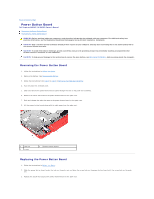
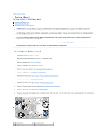
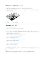
5 audio-board cable 6 USB-board cable 13. Remove the two screws that secure the system board to the computer base. 14. Lift the system board at an angle and release the connectors on the system board from the slots on the computer base. NOTE: Based on the selection you made at the time of purchase of your computer, the dimensions of the system board and the location of the system board components may vary. 1 screws (2) 2 system board Replacing the System Board 1. Follow the instructions in Before You Begin. 2. Slide the connectors on the system board into the slots on the computer base. 3. Replace the two screws that secure the system board to the computer base. 4. Connect the display cable, speakers cable, audio-board cable, USB-board cable, coin-cell battery cable, and AC-adapter cable to the connectors on the system board. 5. Replace the processor. See Replacing the Processor Module. 6. Replace the thermal cooling assembly. See Replacing the Thermal Cooling Assembly. 7. Follow the instructions from step 5 to step 6 in Replacing the Hard Drive. 8. Replace the Mini-Card. See Replacing the Mini-Card. 9. Follow the instructions from step 3 to step 7 in Replacing the Palm-Rest Assembly. 10. Replace the optical drive. See Replacing the Optical Drive. 11. Replace the memory module(s). See Replacing the Memory Module(s). 12. Replace the keyboard. See Replacing the Keyboard. 13. Replace the battery. See Replacing the Battery. 14. Replace any removed cards or blanks in the 3-in-1 media card reader. CAUTION: Before turning on the computer, replace all screws and ensure that no stray screws remain inside the computer. Failure to do so may result in damage to the computer. 15. Turn on the computer. NOTE: After you have replaced the system board, enter the computer Service Tag into the BIOS of the replacement system board.
-
 1
1 -
2
-
3
-
4
-
5
-
6
-
7
-
8
-
9
-
10
-
11
-
12
-
13
-
14
-
15
-
16
-
17
-
18
-
19
-
20
-
21
-
22
-
23
-
24
-
25
-
26
-
27
-
28
-
29
-
30
-
31
-
32
-
33
-
 34
34 -
 35
35 -
 36
36 -
 37
37 -
 38
38 -
 39
39 -
 40
40 -
 41
41 -
 42
42 -
 43
43
 |
 |
