Dell Inspiron 300m Service Manual
Dell Inspiron 300m Manual
 |
View all Dell Inspiron 300m manuals
Add to My Manuals
Save this manual to your list of manuals |
Dell Inspiron 300m manual content summary:
- Dell Inspiron 300m | Service Manual - Page 1
Dell™ Inspiron™ 300m Service Manual Before You Begin Dell Diagnostics System Components Battery Memory, Modem, and Mini PCI Card Modules Keyboard Palm Rest Hard Drive Hinge Covers and Display Assembly Keyboard Tray Reserve Battery Speakers Bluetooth™ Module Cooling Fan Battery Latches System Board - Dell Inspiron 300m | Service Manual - Page 2
Page Battery Latches Dell™ Inspiron™ 300m Service Manual Removing the Battery Latches Replacing the Battery Latches Removing the Battery Latches CAUTION: Before you begin any of the procedures in this section, follow the safety instructions in the Owner's Manual. NOTICE: Disconnect the computer and - Dell Inspiron 300m | Service Manual - Page 3
lock latch 3 bottom case 4 battery lock latch 5 spring 6 battery-latch release button Replacing the Battery Latches 1. Snap in the new latch button from behind the bottom case, making certain that the snap tabs are fully engaged in the latch. NOTE: The battery latch release has springs and should - Dell Inspiron 300m | Service Manual - Page 4
Battery Dell™ Inspiron™ 300m Service Manual Removing a Battery Installing the Battery Removing a Battery CAUTION: Before performing these procedures, disconnect the modem from the telephone wall jack. CAUTION: Before you begin any of the procedures in this section, follow the safety instructions - Dell Inspiron 300m | Service Manual - Page 5
1 optional extended battery Back to Contents Page - Dell Inspiron 300m | Service Manual - Page 6
to Contents Page Before You Begin Dell™ Inspiron™ 300m Service Manual Recommended Tools Shutting Down Your Computer Computer Orientation Screw Identification Placemat This section provides procedures for removing and installing the components in your computer. Unless otherwise noted, each procedure - Dell Inspiron 300m | Service Manual - Page 7
main battery before you service the computer. 10. Slide and hold the battery-bay latch release on the bottom of the computer, and then remove the battery from the bay. 1 battery latch release (2) 11. Remove any installed modules, including a second battery, if installed. 12. Remove the hard drive - Dell Inspiron 300m | Service Manual - Page 8
Screw Identification Placemat When you are removing and replacing components, photocopy the placemat as a with its corresponding hole, and avoid overtightening. Keyboard: (4 each) Palm Rest: (9 each) Display Assembly: (2 each) Keyboard Tray: (5 each) Hard Drive: (4 each) System Board: (3 each - Dell Inspiron 300m | Service Manual - Page 9
Modem Card: (1 each) Cooling Fan: (4 each) Speakers: (1 each) Bluetooth™ Module (1 each) Back to Contents Page - Dell Inspiron 300m | Service Manual - Page 10
the BIOS Dell™ Inspiron™ 300m Service Manual To update the basic input/output system (BIOS): 1. Go to support.dell.com. If this is your first time to use the website, complete the one-time registration. 2. Enter the Service Tag for your computer or select the appropriate Dell™ computer. Click - Dell Inspiron 300m | Service Manual - Page 11
Back to Contents Page Bluetooth™ Module Dell™ Inspiron™ 300m Service Manual Replacing the Bluetooth Module CAUTION: Before you begin any of the procedures in this section, follow the safety instructions in the Owner's Manual. 1. Remove the M2 x 5-mm screw. 2. Disconnect the cable from the system - Dell Inspiron 300m | Service Manual - Page 12
Page Dell Diagnostics Dell™ Inspiron™ 300m Service Manual When to Use the Dell Diagnostics Starting the Dell Diagnostics When to Use the Dell Diagnostics If you experience a problem with your computer, perform the checks in the "Solving Problems" section in your User's Guide or Owner's Manual and - Dell Inspiron 300m | Service Manual - Page 13
. Write down the error code and problem description and follow the instructions on the screen. If you cannot resolve the error condition, contact Dell. See your User's Guide or Owner's Manual for contact information. NOTE: The Service Tag for your computer is located at the top of each test screen - Dell Inspiron 300m | Service Manual - Page 14
Covers and Display Assembly Dell™ Inspiron™ 300m Service Manual Hinge Covers Display Assembly Hinge Covers Removing the Hinge Covers CAUTION: Before you begin any of the procedures in this section, follow the safety instructions in the Owner's Manual. 1. Remove the battery. 2. On the inside of the - Dell Inspiron 300m | Service Manual - Page 15
Display Assembly Removing the Display Assembly CAUTION: Before you begin any of the procedures in this section, follow the safety instructions in the Owner's Manual. NOTICE: Disconnect the computer and any attached devices from electrical outlets. NOTICE: To avoid ESD, ground yourself by using a - Dell Inspiron 300m | Service Manual - Page 16
board. 5. If a tape secured the signal connector, replace it and connect the signal cable to the system board. 6. Close the display and turn the computer over. 7. Replace the two M3 x 5-mm screws from the bottom of the computer. 8. Replace the keyboard. 9. Replace the battery. Back to Contents Page - Dell Inspiron 300m | Service Manual - Page 17
Back to Contents Page Cooling Fan Dell™ Inspiron™ 300m Service Manual Removing the Cooling Fan CAUTION: Before you begin any of the procedures in this section, follow the safety instructions in the Owner's Manual. NOTICE: Disconnect the computer and any attached devices from electrical outlets. - Dell Inspiron 300m | Service Manual - Page 18
Back to Contents Page - Dell Inspiron 300m | Service Manual - Page 19
Back to Contents Page Hard Drive Dell™ Inspiron™ 300m Service Manual Removing the Hard Drive Replacing the Hard Drive Removing the Hard Drive CAUTION: Before you begin any of the procedures in this section, follow the safety instructions in the Owner's Manual. NOTICE: Disconnect the computer and any - Dell Inspiron 300m | Service Manual - Page 20
Replacing the Hard Drive 1. Connect the hard drive connector to the system board. 2. Position the hard drive on the bottom case and tighten the four M2 x 5.5-mm screws to the bottom case. NOTE: The rubber grommets help you avoid overtightening the screws. Back to Contents Page - Dell Inspiron 300m | Service Manual - Page 21
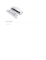
to Contents Page Keyboard Dell™ Inspiron™ 300m Service Manual Removing the Keyboard Replacing the Keyboard Removing the Keyboard CAUTION: Before you begin any of the procedures in this section, follow the safety instructions in the Owner's Manual. NOTICE: Disconnect the computer and any attached - Dell Inspiron 300m | Service Manual - Page 22
ZIF connector tabs toward the back of the computer. 1 ZIF connector 2 keyboard flex cable 3 ZIF connector tabs (2) 8. Remove the keyboard flex cable from the ZIF connector. 9. Lift the keyboard up and out of the computer. Replacing the Keyboard 1. Place the keyboard face-down on the palm rest, with - Dell Inspiron 300m | Service Manual - Page 23
right keys to help control tab/slot alignment. When the keyboard appears to be completely seated, confirm that the front edge of the keyboard is aligned with the edge of the palm rest before proceeding. 7. Replace the four M2 x 4-mm screws on the bottom of the computer. Back to Contents Page - Dell Inspiron 300m | Service Manual - Page 24
Contents Page Keyboard Tray Dell™ Inspiron™ 300m Service Manual Removing the Keyboard Tray Replacing the Keyboard Tray Removing the Keyboard Tray CAUTION: Before you begin any of the procedures in this section, follow the safety instructions in the Owner's Manual. NOTICE: Disconnect the computer and - Dell Inspiron 300m | Service Manual - Page 25
1. Replace the keyboard tray. 2. Route the antenna cables through the oval opening on the keyboard tray. 1 antenna cable connectors 2 oval opening on keyboard tray 3. Reinstall the five M2 x 4-mm screws that secure the keyboard tray to the system board. Back to Contents Page - Dell Inspiron 300m | Service Manual - Page 26
Dell™ Inspiron™ 300m Service Manual NOTE: The part numbers listed below are subject to change. Bottom Plastics Assembly G0767 H0163 H0164 T2913 U2737 battery latch kit bottom LCD-cover assembly memory door bottom plastics assembly (TAA-compliant) bottom plastics assembly (non-TAA version) Power - Dell Inspiron 300m | Service Manual - Page 27
G0810 H0192 J0045 Memory 3Y180 3Y182 0K963 7N020 Modem Y0231 System Board T2907 U2733 Wireless 2U381 9Y200 H0294 J0846 N0498 Screws 2013T 6K709 6R788 7T775 8T707 98MKC Speaker 7C552 Palm Rest Assembly G0808 Back to Contents Page left hinge cover right hinge cover 12.1 LCD hinge up assembly 128 - Dell Inspiron 300m | Service Manual - Page 28
Page Palm Rest Dell™ Inspiron™ 300m Service Manual Removing the Palm Rest Replacing the Palm Rest Removing the Palm Rest CAUTION: Before you begin any of the procedures in this section, follow the safety instructions in the Owner's Manual. NOTICE: Disconnect the computer and any attached devices - Dell Inspiron 300m | Service Manual - Page 29
ZIF connector 3 palm rest 8. Lift the palm rest up and out of the computer. Replacing the Palm Rest To aid with proper flex cable connection, a locator line has been added near the end of the palm-rest flex cable. When replacing the palm-rest flex cable, press the cable into the connector until the - Dell Inspiron 300m | Service Manual - Page 30
Back to Contents Page - Dell Inspiron 300m | Service Manual - Page 31
Back to Contents Page Pin Assignments for I/O Connectors Dell™ Inspiron™ 300m Service Manual Pin Assignments for the Computer Pin Assignments for the Media Base Pin Assignments for the Computer USB Connector 2.0 Pin Signal 1 VCC 2 Data- 3 Data+ 4 GND Video Connector Pin Signal 1 RED - Dell Inspiron 300m | Service Manual - Page 32
1 TPB- 2 TPB+ 3 TPA- 4 TPA+ Pin Assignments for the Media Base Docking Connector Pin Signal 1 DCK3_DOCK_IN2* 3 SYS_DCIN* 5 VDC 7 VDC 9 VDC 11 KBC3_ADID_CLK 13 GND 15 PIO3_SLCT 17 PIO3_AUTOFD* 19 PIO3_ERROR* 21 PIO3_INIT* 23 PIO3_SLCTIN* 25 GND 27 - Dell Inspiron 300m | Service Manual - Page 33
61 SIO3_R11* 63 SIO3_DSR1* 65 SIO3_DSR1* 67 SIO3_DCD1* 69 DCK_NICOMVDC 71 GND 73 LAN3_DCK_TRD2N 75 LAN3_DCK_TRD2P 77 LAN3_DCK_TRD0N 79 LAN3_DCK_TRD0P 81 GND 83 PWRON_CHG 85 DCK_VOLDN* 87 GND 89 USB3_P6- 91 USB3_P6+ 93 GND 95 1394_TPB- 97 1394_TPB+ 99 DCK_DETECT* 62 64 66 68 70 72 74 76 78 80 82 84 - Dell Inspiron 300m | Service Manual - Page 34
7 PD5F 8 PD6F 9 PD7F 16 17 18-25 INIT*/DIR* SLCT_IN/*STEP* GND Video Connector Pin Signal 1 RED 2 GREEN 3 BLUE 4 NC 5 GND 6 GND 7 GND 8 GND Pin Signal 9 CRT_VCC 10 GND 11 NC 12 DAT_DDC2 13 HSYNC 14 VSYNC 15 CLK_DDC2 Serial Connector Pin Signal 1 DCD* 2 - Dell Inspiron 300m | Service Manual - Page 35
USB Connector 2.0 (2) Pin Signal 1 VCC 2 Data- 3 Data+ 4 GND Back to Contents Page - Dell Inspiron 300m | Service Manual - Page 36
Page Reserve Battery Dell™ Inspiron™ 300m Service Manual Removing the Reserve Battery Replacing the Reserve Battery Removing the Reserve Battery CAUTION: Before you begin any of the procedures in this section, follow the safety instructions in the Owner's Manual. NOTICE: Disconnect the computer and - Dell Inspiron 300m | Service Manual - Page 37
Replacing the Reserve Battery 1. Connect the reserve battery connector to the system board connector. 2. Press the reserve battery into place on the bottom case. 3. Ensure that the cable is routed correctly as shown to avoid damaging the cable. 1 reserve battery cable 4. Connect the speaker - Dell Inspiron 300m | Service Manual - Page 38
Back to Contents Page Speakers Dell™ Inspiron™ 300m Service Manual Removing the Speakers CAUTION: Before you begin any of the procedures in this section, follow the safety instructions in the Owner's Manual. NOTICE: Disconnect the computer and any attached devices from electrical outlets. NOTICE: To - Dell Inspiron 300m | Service Manual - Page 39
Back to Contents Page - Dell Inspiron 300m | Service Manual - Page 40
Page System Board Dell™ Inspiron™ 300m Service Manual Removing the System Board Replacing the System Board Removing the System Board CAUTION: Before you begin any of the procedures in this section, follow the safety instructions in the Owner's Manual. NOTICE: Disconnect the computer and any attached - Dell Inspiron 300m | Service Manual - Page 41
together. 1 wireless antenna 2. Reconnect all the cables to the system board ZIF connectors. 3. Reinstall the three M2 x 4-mm screws that secure the system board to the bottom case. NOTE: After replacing the system board, enter the computer Service Tag into the BIOS of the replacement system - Dell Inspiron 300m | Service Manual - Page 42
Inspiron™ 300m Service Manual NOTICE: Only a certified service technician should perform repairs on your computer. Damage due to servicing that is not authorized by Dell is not covered by your warranty. NOTICE: Unless otherwise noted, each procedure in this manual assumes that a part can be replaced - Dell Inspiron 300m | Service Manual - Page 43
Back to Contents Page Dell™ Inspiron™ 300m Service Manual NOTE: A NOTE indicates important information that helps you make better use of your computer. NOTICE: A NOTICE indicates either potential damage to hardware or loss of data and tells you how to avoid the problem. CAUTION: A CAUTION indicates - Dell Inspiron 300m | Service Manual - Page 44
Modules Dell™ Inspiron™ 300m Service Manual Adding Memory Replacing a Modem Adding a Mini PCI Card Adding Memory You can increase your computer memory by installing a memory module on the system board. See the "Specifications" section in your Owner's Manual for information on the memory supported by - Dell Inspiron 300m | Service Manual - Page 45
8. If you are replacing a memory module, remove the existing module. NOTICE: Handle components and cards by their edges, and avoid touching pins and contacts. Ground yourself by touching a metal connector on the back of the computer. Continue to ground yourself periodically during this procedure. a. - Dell Inspiron 300m | Service Manual - Page 46
10. Replace the cover. NOTICE: If the cover is difficult to close, remove the module and reinstall it. Forcing the cover to close may damage your computer. 1 captive screw (2) 2 memory module cover 11. Insert the battery into the battery bay, or connect the AC adapter to your computer and an - Dell Inspiron 300m | Service Manual - Page 47
1 captive screw (2) 2 cover 8. If a modem is not already installed, go to step 10. 9. If you are replacing a modem, remove the existing modem: a. Remove the screw securing the modem to the system board, and set it aside. b. Pull straight up on the attached pull-tab to lift the modem - Dell Inspiron 300m | Service Manual - Page 48
to a media base (docked), undock it. See the documentation that came with the media base for instructions. 4. Disconnect the computer from the electrical outlet. 5. Wait 10 to 20 seconds and then disconnect any attached devices. 6. Remove any installed PC Card or blanks, battery, and devices. NOTICE - Dell Inspiron 300m | Service Manual - Page 49
card out of its connector. NOTICE: To avoid damaging the Mini PCI card, never place cables on top of or under the card. 10. To replace a Mini PCI card, align the card with the connector at a 45-degree angle, and press the Mini PCI card into the connector. 11. Lower the - Dell Inspiron 300m | Service Manual - Page 50
Mini PCI card. NOTICE: The connectors are keyed for correct insertion. If you feel resistance, check the connectors and realign the card. 1 cable connector 14. Replace the cover and tighten the screws. Back to Contents Page
-
 1
1 -
 2
2 -
 3
3 -
 4
4 -
 5
5 -
 6
6 -
 7
7 -
8
-
9
-
10
-
11
-
12
-
13
-
14
-
15
-
16
-
17
-
18
-
19
-
20
-
21
-
22
-
23
-
24
-
25
-
26
-
27
-
28
-
29
-
30
-
31
-
32
-
33
-
34
-
35
-
36
-
37
-
38
-
39
-
40
-
41
-
42
-
43
-
44
-
45
-
46
-
47
-
48
-
49
-
50
 |
 |
Dell™ Inspiron™ 300m Service Manual
Notes, Notices, and Cautions
Information in this document is subject to change without notice.
©
2003-
2005 Dell Inc. All rights reserved.
Reproduction in any manner whatsoever without the written permission of Dell Inc.
is strictly forbidden.
Trademarks used in this text:
Dell
, the
DELL
logo,
ExpressCharge
, and
Latitude
are trademarks of Dell Inc.;
Microsoft
and
Windows
are registered trademarks of Microsoft
Corporation;
Intel
is a registered trademark of Intel Corporation;
Bluetooth
is a trademark owned by Bluetooth SIG, Inc. and is used by Dell Inc. under license.
Other trademarks and trade names may be used in this document to refer to either the entities claiming the marks and names or their products. Dell Inc. disclaims any
proprietary interest in trademarks and trade names other than its own.
May 2005 Rev. A02
Before You Begin
Dell Diagnostics
System Components
Battery
Memory, Modem, and Mini PCI Card Modules
Keyboard
Palm Rest
Hard Drive
Hinge Covers and Display Assembly
Keyboard Tray
Reserve Battery
Speakers
Bluetooth™ Module
Cooling Fan
Battery Latches
System Board
Flashing the BIOS
Pin Assignments for I/O Connectors
Mini Recommended Spares List
NOTE:
A NOTE indicates important information that helps you make better use of your computer.
NOTICE:
A NOTICE indicates either potential damage to hardware or loss of data and tells you how to avoid the problem.
CAUTION:
A CAUTION indicates a potential for property damage, personal injury, or death.