Dell Inspiron 300m Service Manual - Page 41
Replacing the System Board - bios
 |
View all Dell Inspiron 300m manuals
Add to My Manuals
Save this manual to your list of manuals |
Page 41 highlights
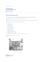
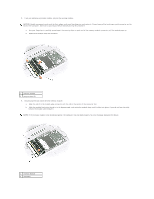
3 status light (LED) cable 4 ZIF connector 12. Disconnect the left and right speakers from their system board connectors. NOTE: The Reserve battery should be attached on the memory chip surface during transportation to the repair center. 13. Remove the reserve battery. 14. Disconnect the Bluetooth cable from the system board, if a Bluetooth™ device is present. 15. Lift the ZIF connector, and remove the status light (LED) cable from its ZIF connector on the system board. 16. Lift the system board up, from the right side, and out of the bottom case. Replacing the System Board 1. Place the system board in the bottom case. NOTE: Route cables so that they will not be crimped or pinched when the complete assembly is put back together. 1 wireless antenna 2. Reconnect all the cables to the system board ZIF connectors. 3. Reinstall the three M2 x 4-mm screws that secure the system board to the bottom case. NOTE: After replacing the system board, enter the computer Service Tag into the BIOS of the replacement system board. Back to Contents Page
-
 1
1 -
2
-
3
-
4
-
5
-
6
-
7
-
8
-
9
-
10
-
11
-
12
-
13
-
14
-
15
-
16
-
17
-
18
-
19
-
20
-
21
-
22
-
23
-
24
-
25
-
26
-
27
-
28
-
29
-
30
-
31
-
32
-
33
-
34
-
35
-
 36
36 -
 37
37 -
 38
38 -
 39
39 -
 40
40 -
 41
41 -
 42
42 -
 43
43 -
 44
44 -
 45
45 -
 46
46 -
47
-
48
-
49
-
50
 |
 |
