Dell Inspiron 9100 Service Manual
Dell Inspiron 9100 Manual
 |
View all Dell Inspiron 9100 manuals
Add to My Manuals
Save this manual to your list of manuals |
Dell Inspiron 9100 manual content summary:
- Dell Inspiron 9100 | Service Manual - Page 1
Service Manual Dell™ Inspiron™ XPS and Inspiron 9100 Service Manual Before You Begin Memory Module, Mini PCI Card, and Devices System Components Subwoofer Bluetooth™ Card Hard Drive Fans Hinge Covers Keyboard Modem Reserve Battery Display Assembly and Display Latch Keyboard Bracket Palm Rest Video - Dell Inspiron 9100 | Service Manual - Page 2
Dell Inspiron XPS and Inspiron 9100 Service Manual Back to Contents Page Before You Begin Dell™ Inspiron™ XPS and Inspiron 9100 Service Manual metal surface. CAUTION: Handle components and cards with care. Do not touch the components or contacts on a card. Hold a card by its edges or by its metal - Dell Inspiron 9100 | Service Manual - Page 3
damaging the system board, you must remove the main battery before you service the computer. 10. Slide and hold the battery-bay latch release on the bottom of the computer, and then remove the battery from the bay. file:///F|/Service%20Manuals/Dell/Inspiron/9100/begin.htm (2 of 7) [2/28/2004 7:45 - Dell Inspiron 9100 | Service Manual - Page 4
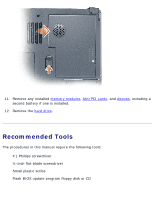
Before You Begin: Dell Inspiron XPS and Inspiron 9100 Service Manual 11. Remove any installed memory modules, Mini PCI cards, and devices, including a second battery if one is installed. 12. Remove the hard drive. Recommended Tools The procedures in this manual require the following tools: q #1 - Dell Inspiron 9100 | Service Manual - Page 5
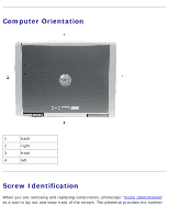
Manual Computer Orientation 1 back 2 right 3 front 4 left Screw Identification When you are removing and replacing components, photocopy "Screw Identification" as a tool to lay out and keep track of the screws. The placemat provides the number file:///F|/Service%20Manuals/Dell/Inspiron/9100 - Dell Inspiron 9100 | Service Manual - Page 6
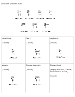
Inspiron XPS and Inspiron 9100 Service Manual of screws and their sizes. Hard Drive: (1 each) Fan 2 (1 each) Keyboard: (2 each) Modem: (1 each) Display Assembly: (4 each) Display Bezel: (display bumpers, 6 each; screw covers, 2 each) (6 each) file:///F|/Service%20Manuals/Dell/Inspiron/9100 - Dell Inspiron 9100 | Service Manual - Page 7
Before You Begin: Dell Inspiron XPS and Inspiron 9100 Service Manual (2 each, shoulder type) Display Panel: (8 each) Display Latch: (2 each) Keyboard Bracket: (4 each) Display Ground Screw: (1 each) file:///F|/Service%20Manuals/Dell/Inspiron/9100/begin.htm (6 of 7) [2/28/2004 7:45:44 AM] - Dell Inspiron 9100 | Service Manual - Page 8
Before You Begin: Dell Inspiron XPS and Inspiron 9100 Service Manual Palm Rest: Video Card: (3 each) (4 each) Speakers: (3 each) (4 each) Display Release Latch: (2 each) System Board: (6 each) Back to Contents Page file:///F|/Service%20Manuals/Dell/Inspiron/9100/begin.htm (7 of 7) [2/28/ - Dell Inspiron 9100 | Service Manual - Page 9
it always has two identical memory modules. 1. Follow the instructions in "Preparing to Work Inside the Computer." 2. Turn the computer over, loosen the captive screw (labeled "M") from the memory module cover, and lift the cover. file:///F|/Service%20Manuals/Dell/Inspiron/9100/upgrades.htm (1 of 14 - Dell Inspiron 9100 | Service Manual - Page 10
Module, Mini PCI Card, and Devices: Dell Inspiron XPS and Inspiron 9100 Service Manual NOTICE: To prevent damage to the memory module connector, do not use tools to spread the securing clips that secure the memory module. 3. If you are replacing a memory module, remove the existing module. NOTICE - Dell Inspiron 9100 | Service Manual - Page 11
you do not feel the click, remove the module and reinstall it. NOTE: If the memory module is not installed properly, the computer does not boot. No error message indicates this failure. 5. Replace the cover and screw. file:///F|/Service%20Manuals/Dell/Inspiron/9100/upgrades.htm (3 of 14) [2/28/2004 - Dell Inspiron 9100 | Service Manual - Page 12
battery bay, or connect the AC adapter to your computer and an electrical outlet. 7. Turn on the computer. As the computer boots, it detects the additional memory and automatically updates the system configuration information. Mini PCI Card file:///F|/Service%20Manuals/Dell/Inspiron/9100/upgrades - Dell Inspiron 9100 | Service Manual - Page 13
Mini PCI card with your computer, the card is already installed. 1. Follow the instructions in "Preparing to Work Inside the Computer." 2. Turn over the computer. 3. Unscrew the captive screw labeled "C" and remove the Mini PCI card cover. file:///F|/Service%20Manuals/Dell/Inspiron/9100/upgrades.htm - Dell Inspiron 9100 | Service Manual - Page 14
: Dell Inspiron XPS and Inspiron 9100 Service Manual 4. If a Mini PCI card is not already installed, go to step 5. If you are replacing a Mini PCI card, remove the existing card: a. Disconnect the antenna cables from the Mini PCI card. file:///F|/Service%20Manuals/Dell/Inspiron/9100/upgrades.htm - Dell Inspiron 9100 | Service Manual - Page 15
Memory Module, Mini PCI Card, and Devices: Dell Inspiron XPS and Inspiron 9100 Service Manual 1 antenna cables (2) NOTICE: To prevent damage to the Mini PCI card connector, do not use tools to spread the securing clips that secure the card. b. Release the Mini PCI card by spreading the metal - Dell Inspiron 9100 | Service Manual - Page 16
Memory Module, Mini PCI Card, and Devices: Dell Inspiron XPS and Inspiron 9100 Service Manual 1 securing tabs NOTICE: To avoid damaging the antenna cables or the Mini PCI card, never place the cables under the card. NOTICE: The connectors are keyed to ensure correct insertion. If you feel resistance - Dell Inspiron 9100 | Service Manual - Page 17
Memory Module, Mini PCI Card, and Devices: Dell Inspiron XPS and Inspiron 9100 Service Manual 6. Connect the antenna cables to the Mini PCI card. file:///F|/Service%20Manuals/Dell/Inspiron/9100/upgrades.htm (9 of 14) [2/28/2004 7:45:46 AM] - Dell Inspiron 9100 | Service Manual - Page 18
Your computer ships with an optical drive installed in the module bay. NOTICE: Insert devices into the module bay before you dock and turn on the computer. Removing and Installing Devices While the Computer Is Turned Off file:///F|/Service%20Manuals/Dell/Inspiron/9100/upgrades.htm (10 of 14) [2/28 - Dell Inspiron 9100 | Service Manual - Page 19
Memory Module, Mini PCI Card, and Devices: Dell Inspiron XPS and Inspiron 9100 Service Manual NOTICE: To prevent damage to devices, store them in a latch release 2. Pull the device out of the module bay. file:///F|/Service%20Manuals/Dell/Inspiron/9100/upgrades.htm (11 of 14) [2/28/2004 7:45:46 AM] - Dell Inspiron 9100 | Service Manual - Page 20
Memory Module, Mini PCI Card, and Devices: Dell Inspiron XPS and Inspiron 9100 Service Manual 1 module bay device 2 device latch release 3. Push the new device into the bay until it clicks. Removing . file:///F|/Service%20Manuals/Dell/Inspiron/9100/upgrades.htm (12 of 14) [2/28/2004 7:45:46 AM] - Dell Inspiron 9100 | Service Manual - Page 21
Memory Module, Mini PCI Card, and Devices: Dell Inspiron XPS and Inspiron 9100 Service Manual 1 device latch release 3. Pull the device out of the module bay. file:///F|/Service%20Manuals/Dell/Inspiron/9100/upgrades.htm (13 of 14) [2/28/2004 7:45:46 AM] - Dell Inspiron 9100 | Service Manual - Page 22
Memory Module, Mini PCI Card, and Devices: Dell Inspiron XPS and Inspiron 9100 Service Manual 1 module bay device 2 device latch release 4. Push the new to unlock your computer. Back to Contents Page file:///F|/Service%20Manuals/Dell/Inspiron/9100/upgrades.htm (14 of 14) [2/28/2004 7:45:46 AM] - Dell Inspiron 9100 | Service Manual - Page 23
that is not authorized by Dell is not covered by your warranty. NOTICE: Unless otherwise noted, each procedure in this document assumes that a part can be replaced by performing the removal procedure in reverse order. file:///F|/Service%20Manuals/Dell/Inspiron/9100/system.htm (1 of 2) [2/28/2004 - Dell Inspiron 9100 | Service Manual - Page 24
17 hard drive 7 system board 18 microprocessor thermal-cooling assembly 8 battery and subwoofer assembly 19 video card 9 bottom assembly 20 modem 10 memory 21 reserve battery 11 mini PCI card 22 left hinge cover Back to Contents Page file:///F|/Service%20Manuals/Dell/Inspiron/9100/system - Dell Inspiron 9100 | Service Manual - Page 25
you begin working inside the computer. 3. Remove the subwoofer from the battery: a. Disconnect the subwoofer cable. b. Use a small screwdriver or scribe to release the subwoofer from the compartment in the battery. file:///F|/Service%20Manuals/Dell/Inspiron/9100/woofer.htm (1 of 3) [2/28/2004 7:45 - Dell Inspiron 9100 | Service Manual - Page 26
Subwoofer: Dell Inspiron XPS and Inspiron 9100 Service Manual 1 battery 2 cable 3 subwoofer 4 subwoofer cable connector 4. Insert the subwoofer into the compartment within the battery. file:///F|/Service%20Manuals/Dell/Inspiron/9100/woofer.htm (2 of 3) [2/28/2004 7:45:47 AM] - Dell Inspiron 9100 | Service Manual - Page 27
Subwoofer: Dell Inspiron XPS and Inspiron 9100 Service Manual 1 battery 2 cable 3 subwoofer 4 subwoofer cable connector 5. Connect the cable to the subwoofer connector. 6. Replace the battery in the battery bay. Back to Contents Page file:///F|/Service%20Manuals/Dell/Inspiron/9100/woofer.htm (3 of - Dell Inspiron 9100 | Service Manual - Page 28
Using a plastic scribe or screwdriver, gently pry the Bluetooth card from the plastic guide bracket and the compartment so that you can disconnect the Bluetooth card from its cable and remove it from the computer. file:///F|/Service%20Manuals/Dell/Inspiron/9100/blue.htm (1 of 2) [2/28/2004 7:45:48 - Dell Inspiron 9100 | Service Manual - Page 29
Bluetooth Card: Dell Inspiron XPS and Inspiron 9100 Service Manual 1 Bluetooth card 2 Bluetooth card connector 3 Bluetooth card door Back to Contents Page file:///F|/Service%20Manuals/Dell/Inspiron/9100/blue.htm (2 of 2) [2/28/2004 7:45:48 AM] - Dell Inspiron 9100 | Service Manual - Page 30
CD for your computer to install the drivers and utilities on the new hard drive. 1. Follow the instructions in "Preparing to Work Inside the Computer." 2. Turn over the computer and remove the M3 x 3-mm screw. file:///F|/Service%20Manuals/Dell/Inspiron/9100/hdd.htm (1 of 3) [2/28/2004 7:45:49 - Dell Inspiron 9100 | Service Manual - Page 31
Hard Drive: Dell Inspiron XPS and Inspiron 9100 Service Manual 1 M3 x 3-mm screw 2 hard drive NOTICE: When the hard drive is not in the computer, store it in protective antistatic packaging. See "Protecting Against Electrostatic Discharge" in your Owner's Manual. 3. Slide the hard drive out of the - Dell Inspiron 9100 | Service Manual - Page 32
Hard Drive: Dell Inspiron XPS and Inspiron 9100 Service Manual 6. Replace and tighten the screw. 7. Use the Operating System CD to install the operating system for your computer. For instructions, see "Reinstalling Microsoft Windows XP" in your Owner's Manual. 8. Use the Drivers and Utilities CD to - Dell Inspiron 9100 | Service Manual - Page 33
the instructions in "Preparing to Work Inside the Computer." 2. Turn over the computer. 3. Unscrew the two captive screws labeled "F2," lift up the fan cover, and remove it from the computer. NOTE: This fan cover comes off over the audio connectors. file:///F|/Service%20Manuals/Dell/Inspiron/9100 - Dell Inspiron 9100 | Service Manual - Page 34
Fans: Dell Inspiron XPS and Inspiron 9100 Service Manual 1 captive screws (2) 2 fan cover 3 audio connectors 4. Remove the M2.5 x 6-mm screw on the fan and lift up the fan release lever. file:///F|/Service%20Manuals/Dell/Inspiron/9100/fan.htm (2 of 4) [2/28/2004 7:45:50 AM] - Dell Inspiron 9100 | Service Manual - Page 35
Fans: Dell Inspiron XPS and Inspiron 9100 Service Manual 1 fan 2 fan release lever 3 M2.5 x 6-mm screw 5. Use the fan release lever to lift the fan out of the computer. When replacing fan 2, press down on the fan surface labeled "Press here" to securely seat the fan in place. To remove fan 3: 1. - Dell Inspiron 9100 | Service Manual - Page 36
Fans: Dell Inspiron XPS and Inspiron 9100 Service Manual NOTE: The cover on this fan is not removable. It remains attached to the fan. 1 captive screws (2) 2 fan cover Back to Contents Page file:///F|/Service%20Manuals/Dell/Inspiron/9100/fan.htm (4 of 4) [2/28/2004 7:45:50 AM] - Dell Inspiron 9100 | Service Manual - Page 37
Hinge Covers: Dell Inspiron XPS and Inspiron 9100 Service Manual Back to Contents Page Hinge Covers Dell™ Inspiron™ XPS and Inspiron 9100 Service Manual CAUTION: Before working inside your computer, read the safety instructions in your Owner's Manual. NOTICE: To avoid electrostatic discharge, ground - Dell Inspiron 9100 | Service Manual - Page 38
Inspiron 9100 Service Manual 1 left hinge cover 2 right hinge cover 3. Remove the center hinge cover: a. Close the display. b. Facing the front of the computer, press in on the two hinge cover snaps and pull them up slightly to disengage them. file:///F|/Service%20Manuals/Dell/Inspiron/9100/hinge - Dell Inspiron 9100 | Service Manual - Page 39
Hinge Covers: Dell Inspiron XPS and Inspiron 9100 Service Manual 1 hinge cover snaps (2) c. Open the display all the way (180 degrees) so the center-hinge-cover flex cable from the system board connector. file:///F|/Service%20Manuals/Dell/Inspiron/9100/hinge.htm (3 of 4) [2/28/2004 7:45:51 AM] - Dell Inspiron 9100 | Service Manual - Page 40
Hinge Covers: Dell Inspiron XPS and Inspiron 9100 Service Manual 1 center hinge cover 2 center-hinge-cover flex cable and pull-tab 3 system board connector Back to Contents Page file:///F|/Service%20Manuals/Dell/Inspiron/9100/hinge.htm (4 of 4) [2/28/2004 7:45:51 AM] - Dell Inspiron 9100 | Service Manual - Page 41
Keyboard: Dell Inspiron XPS and Inspiron 9100 Service Manual Back to Contents Page Keyboard Dell™ Inspiron™ XPS and Inspiron 9100 Service Manual CAUTION: Before performing the following procedures, read the safety instructions in your Owner's Manual. NOTICE: To avoid electrostatic discharge, ground - Dell Inspiron 9100 | Service Manual - Page 42
Keyboard: Dell Inspiron XPS and Inspiron 9100 Service Manual 1 keyboard 2 M2.5 x 3-mm screws (2) 3 keyboard connector tab 4 system board connector NOTICE: To avoid scratching the palm rest when replacing the keyboard, hook the four tabs along the front edge of the keyboard into the palm rest, and - Dell Inspiron 9100 | Service Manual - Page 43
Keyboard: Dell Inspiron XPS and Inspiron 9100 Service Manual Back to Contents Page file:///F|/Service%20Manuals/Dell/Inspiron/9100/keyboard.htm (3 of 3) [2/28/2004 7:45:52 AM] - Dell Inspiron 9100 | Service Manual - Page 44
battery before you begin working inside the computer. Removing the Modem 1. Follow the instructions in "Preparing to Work Inside the Computer." 2. Remove the left, right, and center hinge covers. 3. Remove the keyboard. 4. Remove the M2.5 x 3-mm screw. file:///F|/Service%20Manuals/Dell/Inspiron/9100 - Dell Inspiron 9100 | Service Manual - Page 45
Modem: Dell Inspiron XPS and Inspiron 9100 Service Manual 1 M2.5 x 3-mm screw 2 pull-tab 3 modem 4 modem cable 5. Pull up on the pull cable from the system board. 6. Disconnect the modem cable from the modem. file:///F|/Service%20Manuals/Dell/Inspiron/9100/modem.htm (2 of 3) [2/28/2004 7:45:53 AM] - Dell Inspiron 9100 | Service Manual - Page 46
Modem: Dell Inspiron XPS and Inspiron 9100 Service Manual Installing the Modem 1. Connect the modem cable to the modem. NOTICE: Ensure that the modem cable is routed correctly when you replace the modem. NOTICE: Do not press down on the left side of the modem while installing it. 2. Align the - Dell Inspiron 9100 | Service Manual - Page 47
Reserve Battery: Dell Inspiron XPS and Inspiron 9100 Service Manual Back to Contents Page Reserve Battery Dell™ Inspiron™ XPS and Inspiron 9100 Service Manual CAUTION: Before performing the following procedures, read the safety instructions in your Owner's Manual. NOTICE: To avoid electrostatic - Dell Inspiron 9100 | Service Manual - Page 48
and Inspiron 9100 Service Manual 1 reserve battery clip 2 system board connector 3 reserve battery NOTE: Use a scribe to press the reserve battery cable connector into the system board connector when replacing the reserve battery. Back to Contents Page file:///F|/Service%20Manuals/Dell/Inspiron/9100 - Dell Inspiron 9100 | Service Manual - Page 49
." NOTICE: Before turning the computer over and removing the screws, ensure that the display is firmly latched closed. 2. Turn the computer over and remove the four screws (two on each side) labeled "D" on the bottom of the computer. file:///F|/Service%20Manuals/Dell/Inspiron/9100/display.htm (1 of - Dell Inspiron 9100 | Service Manual - Page 50
Inspiron XPS and Inspiron 9100 Service Manual 1 M2.5 x 6-mm screws labeled "D" (4) 3. Turn the computer over and open the display. 4. Remove the left, right, and center hinge covers. 5. Disconnect the antenna cables (pull to separate the connectors). file:///F|/Service%20Manuals/Dell/Inspiron/9100 - Dell Inspiron 9100 | Service Manual - Page 51
Latch: Dell Inspiron XPS and Inspiron 9100 Service Manual 1 display cable 2 antenna cables (2) 3 system board connector 6. Use the pull-tab to disconnect the display cable. 7. Lift the display out of the computer at a 90-degree angle. file:///F|/Service%20Manuals/Dell/Inspiron/9100/display.htm - Dell Inspiron 9100 | Service Manual - Page 52
Display Assembly and Display Latch: Dell Inspiron XPS and Inspiron 9100 Service Manual 1 display Display file:///F|/Service%20Manuals/Dell/Inspiron/9100/display.htm (4 of 11) [2/28/2004 7:45:55 AM] - Dell Inspiron 9100 | Service Manual - Page 53
Display Assembly and Display Latch: Dell Inspiron XPS and Inspiron 9100 Service Manual file:///F|/Service%20Manuals/Dell/Inspiron/9100/display.htm (5 of 11) [2/28/2004 7:45:55 AM] - Dell Inspiron 9100 | Service Manual - Page 54
the instructions in "Preparing to Work Inside the Computer." 2. Remove the display. 3. Remove the six rubber display bumpers and two screw covers. 4. Remove the six M2.5 x 6-mm screws and two M2.5 x 6-mm shoulder screws and remove the display bezel. file:///F|/Service%20Manuals/Dell/Inspiron/9100 - Dell Inspiron 9100 | Service Manual - Page 55
bumpers (6) 3 display bezel 4 M2.5 x 6-mm shoulder screws (2) 5 screw covers (2) Display Panel CAUTION: Before performing the following procedures, read the safety instructions in your Owner's Manual. file:///F|/Service%20Manuals/Dell/Inspiron/9100/display.htm (7 of 11) [2/28/2004 7:45:55 AM] - Dell Inspiron 9100 | Service Manual - Page 56
Latch: Dell Inspiron XPS and Inspiron 9100 Service Manual NOTICE: To avoid electrostatic discharge, ground yourself by using a wrist grounding strap or by touching an unpainted metal surface on the computer. NOTICE: To avoid damaging the system board, you must remove the main battery before you - Dell Inspiron 9100 | Service Manual - Page 57
Display Assembly and Display Latch: Dell Inspiron XPS and Inspiron 9100 Service Manual 2 M2 x 3-mm ground screw 3 M2 x 3-mm screws (8) 4 display flex-cable connector 3 display connector 4 inverter connector file:///F|/Service%20Manuals/Dell/Inspiron/9100/display.htm (9 of 11) [2/28/2004 7:45:55 AM] - Dell Inspiron 9100 | Service Manual - Page 58
battery before you begin working inside the computer. 1. Follow the instructions in "Preparing to Work Inside the Computer." 2. Remove the display. 3. Remove the display bezel. 4. Remove the two M2.5 x 4-mm screws and remove the display latch. file:///F|/Service%20Manuals/Dell/Inspiron/9100/display - Dell Inspiron 9100 | Service Manual - Page 59
Display Assembly and Display Latch: Dell Inspiron XPS and Inspiron 9100 Service Manual 1 M2.5 x 4-mm screws (2) 2 display latch Back to Contents Page file:///F|/Service%20Manuals/Dell/Inspiron/9100/display.htm (11 of 11) [2/28/2004 7:45:55 AM] - Dell Inspiron 9100 | Service Manual - Page 60
Keyboard Bracket: Dell Inspiron XPS and Inspiron 9100 Service Manual Back to Contents Page Keyboard Bracket Dell™ Inspiron™ XPS and Inspiron 9100 Service Manual CAUTION: Before performing the following procedures, read the safety instructions in your Owner's Manual. NOTICE: To avoid electrostatic - Dell Inspiron 9100 | Service Manual - Page 61
Keyboard Bracket: Dell Inspiron XPS and Inspiron 9100 Service Manual 1 FPC cable pull-tab 2 M2.5 x 6-mm screws (4) 3 keyboard bracket Back to Contents Page file:///F|/Service%20Manuals/Dell/Inspiron/9100/keybrack.htm (2 of 2) [2/28/2004 7:45:55 AM] - Dell Inspiron 9100 | Service Manual - Page 62
the left, right, and center hinge covers. 3. Remove the keyboard. 4. Remove the display assembly. 5. Remove the keyboard bracket. 6. Turn over the computer and remove the three M2.5 x 8-mm screws labeled "P." file:///F|/Service%20Manuals/Dell/Inspiron/9100/palmrest.htm (1 of 3) [2/28/2004 7:45:56 - Dell Inspiron 9100 | Service Manual - Page 63
Palm Rest: Dell Inspiron XPS and Inspiron 9100 Service Manual 1 M2.5 x 8-mm screws labeled "P" (3) 7. Turn the computer top-side up and remove the four M2.5 x 6-mm screws labeled "P." 8. Disconnect the touch-pad connector from the system board. 9. Slide the palm rest forward and remove it from the - Dell Inspiron 9100 | Service Manual - Page 64
Palm Rest: Dell Inspiron XPS and Inspiron 9100 Service Manual 1 M2.5 x 6-mm screws (4) 2 touch-pad connector Back to Contents Page file:///F|/Service%20Manuals/Dell/Inspiron/9100/palmrest.htm (3 of 3) [2/28/2004 7:45:56 AM] - Dell Inspiron 9100 | Service Manual - Page 65
Video Card: Dell Inspiron XPS and Inspiron 9100 Service Manual Back to Contents Page Video Card Dell™ Inspiron™ XPS and Inspiron 9100 Service Manual CAUTION: Before performing the following procedures, read the safety instructions in your Owner's Manual. NOTICE: To avoid electrostatic discharge, - Dell Inspiron 9100 | Service Manual - Page 66
Video Card: Dell Inspiron XPS and Inspiron 9100 Service Manual 1 system board connector 2 M2.5 x 6-mm screws (4) 3 video card Back to Contents Page file:///F|/Service%20Manuals/Dell/Inspiron/9100/video.htm (2 of 2) [2/28/2004 7:45:57 AM] - Dell Inspiron 9100 | Service Manual - Page 67
Dell Inspiron XPS and Inspiron 9100 Service Manual Back to Contents Page Microprocessor Thermal-Cooling Assembly Dell™ Inspiron™ XPS and Inspiron 9100 Service Manual Removing the Microprocessor Thermal-Cooling Assembly CAUTION: Before performing the following procedures, read the safety instructions - Dell Inspiron 9100 | Service Manual - Page 68
Microprocessor Thermal-Cooling Assembly: Dell Inspiron XPS and Inspiron 9100 Service Manual 1 microprocessor thermal-cooling assembly 2 captive screws, labeled "1" through "4," in consecutive order. Back to Contents Page file:///F|/Service%20Manuals/Dell/Inspiron/9100/thermal.htm (2 of 2) [2/28/2004 - Dell Inspiron 9100 | Service Manual - Page 69
. 1. Follow the instructions in "Preparing to Work Inside the Computer." 2. Remove the left, right, and center hinge covers. 3. Remove the keyboard. 4. Remove the display assembly. 5. Remove the keyboard bracket. 6. Remove the video card. file:///F|/Service%20Manuals/Dell/Inspiron/9100/cpu.htm (1 of - Dell Inspiron 9100 | Service Manual - Page 70
Module: Dell Inspiron XPS and Inspiron 9100 Service Manual NOTICE: To ensure maximum cooling for the microprocessor, do not touch the heat transfer areas on the microprocessor thermal-cooling assembly. The oils in your skin reduce the heat transfer capability of the thermal pads. 7. Remove the - Dell Inspiron 9100 | Service Manual - Page 71
Microprocessor Module: Dell Inspiron XPS and Inspiron 9100 Service Manual 2 screwdriver (perpendicular to microprocessor Tighten the ZIF socket by turning the cam screw clockwise to secure the microprocessor module to the system board. file:///F|/Service%20Manuals/Dell/Inspiron/9100/cpu.htm (3 of 4) - Dell Inspiron 9100 | Service Manual - Page 72
: Dell Inspiron XPS and Inspiron 9100 Service Manual 3. Perform the steps in "Removing the Microprocessor Module" in reverse order, beginning with step 7. 4. Update the BIOS using a flash BIOS update program floppy disk or CD. For instructions on how to flash the BIOS, see "Flashing the BIOS." Back - Dell Inspiron 9100 | Service Manual - Page 73
Speakers: Dell Inspiron XPS and Inspiron 9100 Service Manual Back to Contents Page Speakers Dell™ Inspiron™ XPS and Inspiron 9100 Service Manual CAUTION: Before performing the following procedures, read the safety instructions in your Owner's Manual. NOTICE: To avoid electrostatic discharge, ground - Dell Inspiron 9100 | Service Manual - Page 74
Speakers: Dell Inspiron XPS and Inspiron 9100 Service Manual 1 M2.5 x 6-mm screws (3) 2 speakers 3 speaker connector Back to Contents Page file:///F|/Service%20Manuals/Dell/Inspiron/9100/speakers.htm (2 of 2) [2/28/2004 7:45:59 AM] - Dell Inspiron 9100 | Service Manual - Page 75
Display Release Latch: Dell Inspiron XPS and Inspiron 9100 Service Manual Back to Contents Page Display Release Latch Dell™ Inspiron™ XPS and Inspiron 9100 Service Manual CAUTION: Before performing the following procedures, read the safety instructions in your Owner's Manual. NOTICE: To avoid - Dell Inspiron 9100 | Service Manual - Page 76
Display Release Latch: Dell Inspiron XPS and Inspiron 9100 Service Manual 1 M2.5 x 6-mm screws (2) 2 display release latch 3 computer base Back to Contents Page file:///F|/Service%20Manuals/Dell/Inspiron/9100/latch.htm (2 of 2) [2/28/2004 7:46:00 AM] - Dell Inspiron 9100 | Service Manual - Page 77
System Board: Dell Inspiron XPS and Inspiron 9100 Service Manual Back to Contents Page System Board Dell™ Inspiron™ XPS and Inspiron 9100 Service Manual Removing the System Board CAUTION: Before performing the following procedures, read the safety instructions in your Owner's Manual. NOTICE: To - Dell Inspiron 9100 | Service Manual - Page 78
System Board: Dell Inspiron XPS and Inspiron 9100 Service Manual 10. Turn over the system and remove the two M2.5 x 6-mm screws from the bottom system board assembly. 1 M2.5 x 6-mm screws (2) 2 system board bottom assembly 11. Turn over the system again and remove the four M2.5 x 6-mm screws from - Dell Inspiron 9100 | Service Manual - Page 79
System Board: Dell Inspiron XPS and Inspiron 9100 Service Manual 1 M2.5 x 6-mm screws (4) 2 system board top assembly 12. With the front of the side and draw the system board assembly out of the computer. file:///F|/Service%20Manuals/Dell/Inspiron/9100/sysboard.htm (3 of 5) [2/28/2004 7:46:01 AM] - Dell Inspiron 9100 | Service Manual - Page 80
System Board: Dell Inspiron XPS and Inspiron 9100 Service Manual 1 system board assembly Installing the System Board 1. Perform all of the steps in "Removing the System Board" in reverse order. NOTICE: Before turning on the computer, replace all screws and ensure that no stray screws remain inside - Dell Inspiron 9100 | Service Manual - Page 81
System Board: Dell Inspiron XPS and Inspiron 9100 Service Manual Back to Contents Page file:///F|/Service%20Manuals/Dell/Inspiron/9100/sysboard.htm (5 of 5) [2/28/2004 7:46:01 AM] - Dell Inspiron 9100 | Service Manual - Page 82
9100 Service Manual Back to Contents Page Flashing the BIOS Dell™ Inspiron™ XPS and Inspiron 9100 Service Manual 1. Ensure that the AC adapter is plugged in and that the main battery is installed properly. NOTE: If you use a BIOS update program CD to flash the BIOS, set up the computer to boot - Dell Inspiron 9100 | Service Manual - Page 83
I/O Connectors Dell™ Inspiron™ XPS and Inspiron 9100 Service Manual USB Connector Video Connector S-Video TV-Out Connector IEEE 1394 Connector DVI-I Connector USB Connector Pin Signal 1 USB5V+ 2 USBP- 3 USBP+ 4 GND Video Connector file:///F|/Service%20Manuals/Dell/Inspiron/9100/pinouts - Dell Inspiron 9100 | Service Manual - Page 84
Inspiron 9100 Service Manual Pin Signal Pin Signal 1 CRT_R 9 5V+ 2 CRT_G 10 GND 3 CRT_B 11 MONITOR_DETECT- 4 NC 12 DDC_DATA 5 GND 13 CRT_HS 6 GND 14 CRT_VS 7 GND 15 DDC_CLK 8 GND S-Video TV-Out Connector S-Video Pin Signal file:///F|/Service%20Manuals/Dell/Inspiron/9100 - Dell Inspiron 9100 | Service Manual - Page 85
for I/O Connectors: Dell Inspiron XPS and Inspiron 9100 Service Manual 1 GND 2 GND 3 DLUMA-L 4 DCRMA-L Composite Video Pin Signal 5 NC 6 DCMPS-L 7 GND IEEE 1394 Connector Pin Signal 1 TPB- 2 TPB+ 3 TPA- 4 TPA+ file:///F|/Service%20Manuals/Dell/Inspiron/9100/pinouts.htm - Dell Inspiron 9100 | Service Manual - Page 86
Pin Assignments for I/O Connectors: Dell Inspiron XPS and Inspiron 9100 Service Manual DVI-I Connector Pin Signal Pin Signal 1 TMDS DATA2- 13 TMDS DATA3+ 2 TMDS DATA2+ 14 +5V 3 TMDS DATA2/4 SHLD 15 GND (FOR +5V) 4 TMDS DATA4- 16 - Dell Inspiron 9100 | Service Manual - Page 87
Pin Assignments for I/O Connectors: Dell Inspiron XPS and Inspiron 9100 Service Manual C5 ANALOG COM GND RET Back to Contents Page file:///F|/Service%20Manuals/Dell/Inspiron/9100/pinouts.htm (5 of 5) [2/28/2004 7:46:02 AM]
-
 1
1 -
 2
2 -
 3
3 -
 4
4 -
 5
5 -
 6
6 -
 7
7 -
8
-
9
-
10
-
11
-
12
-
13
-
14
-
15
-
16
-
17
-
18
-
19
-
20
-
21
-
22
-
23
-
24
-
25
-
26
-
27
-
28
-
29
-
30
-
31
-
32
-
33
-
34
-
35
-
36
-
37
-
38
-
39
-
40
-
41
-
42
-
43
-
44
-
45
-
46
-
47
-
48
-
49
-
50
-
51
-
52
-
53
-
54
-
55
-
56
-
57
-
58
-
59
-
60
-
61
-
62
-
63
-
64
-
65
-
66
-
67
-
68
-
69
-
70
-
71
-
72
-
73
-
74
-
75
-
76
-
77
-
78
-
79
-
80
-
81
-
82
-
83
-
84
-
85
-
86
-
87
 |
 |

Dell Inspiron XPS and Inspiron 9100 Service Manual
Dell™ Inspiron™ XPS and Inspiron
9100 Service Manual
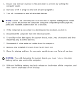
Before You Begin
Memory Module, Mini PCI Card, and Devices
System Components
Subwoofer
Bluetooth™ Card
Hard Drive
Fans
Hinge Covers
Keyboard
Modem
Reserve Battery
Display Assembly and Display Latch
Keyboard Bracket
Palm Rest
Video Card
Microprocessor Thermal-Cooling Assembly
Microprocessor Module
Speakers
Display Release Latch
System Board
Flashing the BIOS
Pin Assignments for I/O Connectors
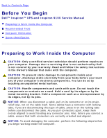
Notes, Notices, and Cautions
NOTE:
A NOTE indicates important information that helps you make better use
of your computer.
NOTICE:
A NOTICE indicates either potential damage to hardware or loss of
data and tells you how to avoid the problem.
file:///F|/Service%20Manuals/Dell/Inspiron/9100/index.htm (1 of 2) [2/28/2004 7:45:34 AM]