Dell Inspiron 9100 Service Manual - Page 50
Disconnect the antenna cables pull to separate the connectors., Remove the left, right, and center
 |
View all Dell Inspiron 9100 manuals
Add to My Manuals
Save this manual to your list of manuals |
Page 50 highlights
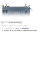
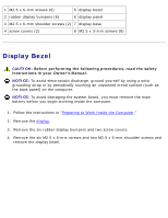
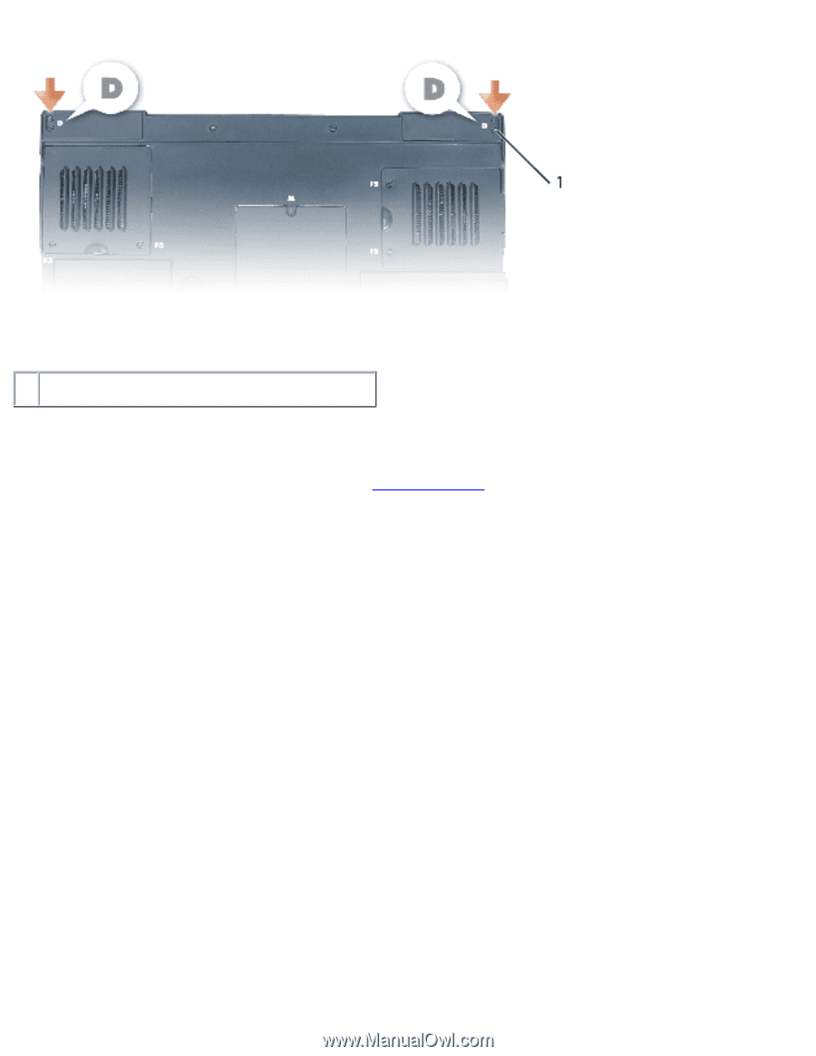
Display Assembly and Display Latch: Dell Inspiron XPS and Inspiron 9100 Service Manual 1 M2.5 x 6-mm screws labeled "D" (4) 3. Turn the computer over and open the display. 4. Remove the left, right, and center hinge covers. 5. Disconnect the antenna cables (pull to separate the connectors). file:///F|/Service%20Manuals/Dell/Inspiron/9100/display.htm (2 of 11) [2/28/2004 7:45:55 AM]
-
 1
1 -
2
-
3
-
4
-
5
-
6
-
7
-
8
-
9
-
10
-
11
-
12
-
13
-
14
-
15
-
16
-
17
-
18
-
19
-
20
-
21
-
22
-
23
-
24
-
25
-
26
-
27
-
28
-
29
-
30
-
31
-
32
-
33
-
34
-
35
-
36
-
37
-
38
-
39
-
40
-
41
-
42
-
43
-
44
-
 45
45 -
 46
46 -
 47
47 -
 48
48 -
 49
49 -
 50
50 -
 51
51 -
 52
52 -
 53
53 -
 54
54 -
 55
55 -
56
-
57
-
58
-
59
-
60
-
61
-
62
-
63
-
64
-
65
-
66
-
67
-
68
-
69
-
70
-
71
-
72
-
73
-
74
-
75
-
76
-
77
-
78
-
79
-
80
-
81
-
82
-
83
-
84
-
85
-
86
-
87
 |
 |
Display Assembly and Display Latch: Dell Inspiron XPS and Inspiron 9100 Service Manual
1
M2.5 x 6-mm screws labeled "D" (4)
3.
Turn the computer over and open the display.
4.
Remove the left, right, and center
hinge covers
.
5.
Disconnect the antenna cables (pull to separate the connectors).
file:///F|/Service%20Manuals/Dell/Inspiron/9100/display.htm (2 of 11) [2/28/2004 7:45:55 AM]