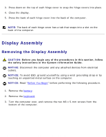
Dell Latitude X300 Service Manual - Page 50
the cables., Disconnect the signal cable from the system board.
 |
View all Dell Latitude X300 manuals
Add to My Manuals
Save this manual to your list of manuals |
Page 50 highlights
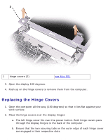
Hinge Covers and Display Assembly: Dell Latitude X300 Service Manual 1 M2 x 6-mm screws (2) 8T707 5. Remove the two M2 x 6-mm screws near the display hinges on the top of the computer. 6. Disconnect both the antenna connectors. NOTICE: Do not pull on the signal cable. Pull the signal connector to disconnect the cables. 7. Disconnect the signal cable from the system board. 8. If a tape secures the signal connector, remove it and disconnect the signal cable from the system board. file:///F|/Service%20Manuals/Dell/Latitude/x300/display.htm (5 of 7) [2/28/2004 8:26:33 AM]
-
 1
1 -
2
-
3
-
4
-
5
-
6
-
7
-
8
-
9
-
10
-
11
-
12
-
13
-
14
-
15
-
16
-
17
-
18
-
19
-
20
-
21
-
22
-
23
-
24
-
25
-
26
-
27
-
28
-
29
-
30
-
31
-
32
-
33
-
34
-
35
-
36
-
37
-
38
-
39
-
40
-
41
-
42
-
43
-
44
-
 45
45 -
 46
46 -
 47
47 -
 48
48 -
 49
49 -
 50
50 -
 51
51 -
 52
52 -
 53
53 -
 54
54 -
 55
55 -
56
-
57
-
58
-
59
-
60
-
61
-
62
-
63
-
64
-
65
-
66
-
67
-
68
-
69
-
70
-
71
-
72
-
73
-
74
-
75
-
76
-
77
-
78
-
79
-
80
-
81
-
82
-
83
-
84
-
85
-
86
-
87
-
88
-
89
 |
 |

Hinge Covers and Display Assembly: Dell Latitude X300 Service Manual
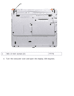
1
M2 x 6-mm screws (2)
8T707
5.
Remove the two M2 x 6-mm screws near the display hinges on the top of the
computer.
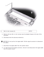
6.
Disconnect both the antenna connectors.
NOTICE:
Do not pull on the signal cable. Pull the signal connector to disconnect
the cables.
7.
Disconnect the signal cable from the system board.
8.
If a tape secures the signal connector, remove it and disconnect the signal cable
from the system board.
file:///F|/Service%20Manuals/Dell/Latitude/x300/display.htm (5 of 7) [2/28/2004 8:26:33 AM]