Dell Studio One 19 1909 Studio One 19 Service Manual
Dell Studio One 19 1909 Manual
 |
View all Dell Studio One 19 1909 manuals
Add to My Manuals
Save this manual to your list of manuals |
Dell Studio One 19 1909 manual content summary:
- Dell Studio One 19 1909 | Studio One 19 Service Manual - Page 1
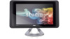
Dell Studio One 19/1909 Service Manual Technical Overview Before You Begin Computer Cover Shield Microphone Stand Memory Module(s) Back I/O Panel Processor Fan and Heat Sink Processor Speakers Drives Cards Inverter System - Dell Studio One 19 1909 | Studio One 19 Service Manual - Page 2
Before You Begin Dell Studio One 19/1909 Service Manual Recommended Tools Turning Off Your Computer Safety Instructions This chapter update program CD l Flash BIOS executable update program on the Dell Support website at support.dell.com Turning Off Your Computer CAUTION: To avoid losing data, - Dell Studio One 19 1909 | Studio One 19 Service Manual - Page 3
2. Turn off your computer (see Turning Off Your Computer). CAUTION: To disconnect a network cable, first unplug the cable from your computer and then unplug the cable from the network device. 3. Disconnect all telephone or network cables from the computer. 4. Disconnect your computer and all - Dell Studio One 19 1909 | Studio One 19 Service Manual - Page 4
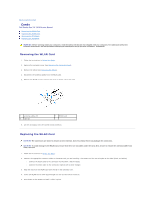
Back to Contents Page Cards Dell Studio One 19/1909 Service Manual Removing the WLAN Card Replacing the the card. Also, ensure to remove the antenna cables from under the card. 1. Follow the instructions in Before You Begin. 2. Connect the appropriate antenna cables to the WLAN card you are - Dell Studio One 19 1909 | Studio One 19 Service Manual - Page 5
that shipped with your computer. For additional safety best practices information, see the Regulatory Compliance Homepage at www.dell.com/regulatory_compliance. 1. Follow the instructions in Before You Begin. 2. Remove the computer cover (see Removing the Computer Cover). 3. Remove the shield (see - Dell Studio One 19 1909 | Studio One 19 Service Manual - Page 6
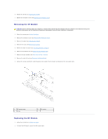
3. Flip the RF module and align the screw hole on the RF module with the screw hole on the chassis. 4. Replace the screw that secures the RF module. 5. Replace the optical drive (see Replacing the Optical Drive). 6. Replace the right speaker (see Replacing the Right Speaker). 7. Replace the - Dell Studio One 19 1909 | Studio One 19 Service Manual - Page 7
Dell Studio One 19/1909 Service Manual dell.com/regulatory_compliance. WARNING: A new battery can explode if it is incorrectly installed. Replace the battery only with the same or equivalent type recommended by the manufacturer. Discard used batteries according to the manufacturer's instructions - Dell Studio One 19 1909 | Studio One 19 Service Manual - Page 8
Replacing the Battery 1. Follow the procedures in Before You Begin. 2. Insert the new battery into the socket with the side labeled "+" facing up and then snap the battery into place. 3. Reconnect the cables to the connectors HDD_POWER and SATA_1 (see System Board Components). 4. Replace the shield - Dell Studio One 19 1909 | Studio One 19 Service Manual - Page 9
Computer Cover Dell Studio One 19/1909 Service Manual Removing the Computer dell.com/regulatory_compliance. WARNING: To guard against electrical shock, always unplug your computer from the electrical outlet before removing the computer cover. CAUTION: Ensure that sufficient space exists to support - Dell Studio One 19 1909 | Studio One 19 Service Manual - Page 10
Back to Contents Page - Dell Studio One 19 1909 | Studio One 19 Service Manual - Page 11
Back to Contents Page Support Assembly Dell Studio One 19/1909 Service Manual Removing the Support Assembly Replacing the Support Assembly WARNING: Before working inside your computer, read the safety information that shipped with your computer. For additional safety best practices information, see - Dell Studio One 19 1909 | Studio One 19 Service Manual - Page 12
1 touch pad cable 3 touch panel cable 2 LVDS cable 4 LCD panel Replacing the Support Assembly 1. Follow the instructions in Before You Begin. 2. Reconnect the following cables to the LCD panel: l LVDS cable from LVDS connector l touch pad cable from the touch pad connector l - Dell Studio One 19 1909 | Studio One 19 Service Manual - Page 13
Back to Contents Page Drives Dell Studio One 19/1909 Service Manual Removing the Hard Drive Replacing the Hard For additional safety best practices information, see the Regulatory Compliance Homepage at www.dell.com/regulatory_compliance. Removing the Hard Drive 1. Follow the procedures in Before - Dell Studio One 19 1909 | Studio One 19 Service Manual - Page 14
1 hard drive 3 hard drive carrier 2 screws (4) Replacing the Hard Drive 1. Follow the procedures in Before You Begin. 2. Prepare the new hard drive for installation and check the documentation that accompanied the drive to verify that the drive is configured for your computer. 3. Align the screws - Dell Studio One 19 1909 | Studio One 19 Service Manual - Page 15
1 optical drive data cable 3 optical drive connector 2 optical drive power cable 4 screws (3) 10. Remove the four screws securing the optical drive to the optical drive carrier. 11. Slide the optical drive out of the optical drive carrier. 1 optical drive carrier 2 screws (4) Replacing the - Dell Studio One 19 1909 | Studio One 19 Service Manual - Page 16
9. Replace the back I/O panel (see Replacing the Back I/O Panel). 10. Replace the stand (see Replacing the Stand). 11. Replace the shield (see Replacing the Shield). 12. Replace the computer cover (see Replacing the Computer Cover). Back to Contents Page - Dell Studio One 19 1909 | Studio One 19 Service Manual - Page 17
to Contents Page Processor Fan and Heat Sink Dell Studio One 19/1909 Service Manual Removing the Heat Sink Replacing the Heat these steps incorrectly could damage your system board. For technical service information, see the Setup Guide. Removing the Heat Sink CAUTION: To ensure maximum cooling for - Dell Studio One 19 1909 | Studio One 19 Service Manual - Page 18
CAUTION: Incorrect alignment of the processor heat sink can cause damage to the system board and processor. 1. Follow the procedures in Before You Begin. NOTE: The original thermal grease can be reused if the original processor and processor heat sink are reinstalled together. If either the - Dell Studio One 19 1909 | Studio One 19 Service Manual - Page 19
6. Lift the processor fan away from the computer and place it in a secure location. Replacing the Processor Fan 1. Follow the procedures in Before You Begin. 2. Connect the processor fan cable to the connector (CPU_FAN1) on the system board. 3. Replace the three screws securing the processor fan. 4. - Dell Studio One 19 1909 | Studio One 19 Service Manual - Page 20
Back to Contents Page Inverter Dell Studio One 19/1909 Service Manual Removing the Inverter Replacing the Inverter WARNING: Before working inside your computer, read the safety information that shipped with your computer. For additional safety best - Dell Studio One 19 1909 | Studio One 19 Service Manual - Page 21
Replacing the Inverter 1. Follow the procedures in Before You Begin. 2. To replace the inverter, connect the two cables from the LCD panel to the inverter. 3. Connect the inverter cable to the system board connector (INVERTER). 4. Replace the two screws that secure the inverter to the chassis. 5. - Dell Studio One 19 1909 | Studio One 19 Service Manual - Page 22
Back to Contents Page Back I/O Panel Dell Studio One 19/1909 Service Manual Removing the Back I/O Panel Replacing the Back I/O Panel WARNING: Before working inside your computer, read the safety information that shipped with your computer. For additional - Dell Studio One 19 1909 | Studio One 19 Service Manual - Page 23
6. Replace the computer cover (see Replacing the Computer Cover). 7. Connect your computer and all attached devices to electrical outlets, and turn them on. Back to Contents Page - Dell Studio One 19 1909 | Studio One 19 Service Manual - Page 24
Back to Contents Page Memory Module(s) Dell Studio One 19/1909 Service Manual Removing Memory Module(s) Replacing Memory Module(s) WARNING: Before working inside your computer, read the safety information that shipped with your computer. For additional safety best - Dell Studio One 19 1909 | Studio One 19 Service Manual - Page 25
10. Check the amount of memory (RAM) listed. Back to Contents Page - Dell Studio One 19 1909 | Studio One 19 Service Manual - Page 26
Back to Contents Page Microphone Dell Studio One 19/1909 Service Manual Removing the Microphone Replacing the Microphone that secure the microphone to the support assembly. 5. Disconnect the cable from the microphone. 6. Lift the microphone away from the support assembly. 1 microphone 3 microphone - Dell Studio One 19 1909 | Studio One 19 Service Manual - Page 27
Dell Studio One 19/1909 Service Manual dell.com/regulatory_compliance. CAUTION: Do not perform the following steps unless you are familiar with hardware removal and replacement. Performing these steps incorrectly could damage your system board. For technical service information, see the Setup Guide - Dell Studio One 19 1909 | Studio One 19 Service Manual - Page 28
Replacing the Processor 1. Follow the procedures in Before You Begin. 2. Lift the release lever to the release position so that the socket is ready for the new processor. CAUTION: Ground yourself by touching an unpainted metal surface or the computer stand. 3. Unpack the new processor. 1 processor - Dell Studio One 19 1909 | Studio One 19 Service Manual - Page 29
11. Apply the new thermal grease to the top of the processor. CAUTION: Ensure that the processor heat sink is correctly seated and secure. 12. Replace the processor heat sink (see Replacing the Heat Sink). 13. Replace the back I/O panel (see Replacing the Back I/O Panel). 14. Replace the stand (see - Dell Studio One 19 1909 | Studio One 19 Service Manual - Page 30
Back to Contents Page Power Supply Unit Dell Studio One 19/1909 Service Manual Removing the Power Supply Unit Replacing the these steps incorrectly could damage your computer. For technical assistance, see the Setup Guide. Removing the Power Supply Unit 1. Follow the procedures in Before You Begin - Dell Studio One 19 1909 | Studio One 19 Service Manual - Page 31
Replacing the Power Supply Unit 1. Follow the procedures in Before You Begin. 2. Replace the four screws that secure the power supply unit to the chassis. 3. Connect the power supply unit cable to the connector (ATX_POWER1) on the system board. 4. Connect the power plug cable to the power supply - Dell Studio One 19 1909 | Studio One 19 Service Manual - Page 32
Back to Contents Page Shield Dell Studio One 19/1909 Service Manual Removing the Shield Replacing the Shield WARNING: Before working inside your computer, read the safety information that shipped with your computer. For additional safety best - Dell Studio One 19 1909 | Studio One 19 Service Manual - Page 33
Back to Contents Page Side I/O Panel Dell Studio One 19/1909 Service Manual Removing the Side I/O Panel Replacing the Side I/O Panel WARNING: Before working inside your computer, read the safety information that shipped with your computer. For additional - Dell Studio One 19 1909 | Studio One 19 Service Manual - Page 34
1 screw 3 connector (SIDE_BOARD_1) 2 connector (F_AUDIO) Replacing the Side I/O Panel 1. Follow the procedures in Before You Begin. 2. To replace the side I/O panel, route the cables back into position and connect them to the connectors (F_AUDIO and SIDE_BOARD_1) on the system board. 3. Slide the - Dell Studio One 19 1909 | Studio One 19 Service Manual - Page 35
Back to Contents Page Speakers Dell Studio One 19/1909 Service Manual Removing the Right Speaker Replacing the Right Speaker Removing the Left Speaker Replacing the Left Speaker WARNING: Before working inside your computer, read the safety - Dell Studio One 19 1909 | Studio One 19 Service Manual - Page 36
devices to electrical outlets, and turn them on. Removing the Left Speaker NOTE: To locate the left speaker, see Inside View of Your Studio One. 1. Follow the procedures in Before You Begin. 2. Remove the computer cover (see Removing the Computer Cover). 3. Remove the shield (see Removing the Shield - Dell Studio One 19 1909 | Studio One 19 Service Manual - Page 37
3. Reconnect the left speaker cable to the connector (SPEAKER_1) on the system board. 4. Replace the four screws that secure the speaker to the chassis. 5. Replace the shield (see Replacing the Shield). 6. Replace the computer cover (see Replacing the Computer Cover). Back to Contents Page - Dell Studio One 19 1909 | Studio One 19 Service Manual - Page 38
Back to Contents Page Stand Dell Studio One 19/1909 Service Manual Removing the Stand Replacing the Stand WARNING: Before working inside your computer, read the safety information that shipped with your computer. For additional safety best - Dell Studio One 19 1909 | Studio One 19 Service Manual - Page 39
- Dell Studio One 19 1909 | Studio One 19 Service Manual - Page 40
Back to Contents Page System Board Dell Studio One 19/1909 Service Manual Removing the System Board Replacing the edges, and avoid touching pins and contacts. Removing the System Board 1. Follow the instructions in Before You Begin. 2. Remove the computer cover (see Removing the Computer Cover). - Dell Studio One 19 1909 | Studio One 19 Service Manual - Page 41
the system board out of the chassis. Replacing the System Board 1. Follow the instructions in Before You Begin. 2. To replace the system board place the system NOTE: After you have replaced the system board, enter the computer Service Tag in the BIOS of the replacement system board. 13. Insert the - Dell Studio One 19 1909 | Studio One 19 Service Manual - Page 42
Contents Page System Fan and Heat Sink Assembly Dell Studio One 19/1909 Service Manual Removing the System Fan and Heat Sink these steps incorrectly could damage your system board. For technical service information, see the Setup Guide. Removing the System Fan and Heat Sink Assembly 1. Follow - Dell Studio One 19 1909 | Studio One 19 Service Manual - Page 43
1 heat sink captive screws (2) 3 system fan cable 2 system fan screws (3) 10. Lift the assembly away from the system board and place it in a secure location. Replacing the System Fan and Heat Sink Assembly 1. Follow the procedures in Before You Begin. 2. To replace the system fan and heat sink - Dell Studio One 19 1909 | Studio One 19 Service Manual - Page 44
Back to Contents Page System Setup Dell Studio One 19/1909 Service Manual Overview Clearing Forgotten Passwords Clearing CMOS . Entering System Setup 1. Turn on (or restart) your computer. 2. When the blue DELL™ logo is displayed, watch for the F2 prompt to appear and then press immediately - Dell Studio One 19 1909 | Studio One 19 Service Manual - Page 45
). Allows you to boot through any other device. Power Management Features ACPI Suspend Type Specifies the suspend type. The default is S3. C1E Support This option allows you to enable or disable the "Enhanced Halt State". Remote Wake Up This option turns on the computer when a user tries - Dell Studio One 19 1909 | Studio One 19 Service Manual - Page 46
sequence, for example, to boot from the CD/DVD drive to run the Dell Diagnostics on the Drivers and Utilities media. On completion of diagnostic tests, the previous any of the procedures in this section, follow the safety instructions that shipped with your computer. WARNING: The computer must be - Dell Studio One 19 1909 | Studio One 19 Service Manual - Page 47
electrical outlets, and turn them on. Clearing CMOS Settings WARNING: Before you begin any of the procedures in this section, follow the safety instructions that shipped with your computer. WARNING: The computer must be disconnected from the electrical outlet to clear the CMOS setting. 1. Follow the - Dell Studio One 19 1909 | Studio One 19 Service Manual - Page 48
Locate the BIOS update file for your computer at the Dell Support website at support.dell.com. NOTE: For non U.S. regions, choose your country/region from the drop-down list at the bottom of the Dell support website and then locate the BIOS update file for your computer. 3. - Dell Studio One 19 1909 | Studio One 19 Service Manual - Page 49
BIOS, set up the computer to boot from a CD before inserting the CD. 2. Insert the BIOS upgrade CD, and restart the computer. Follow the instructions that appear on the screen. The computer continues to boot and updates the new BIOS. When the flash update is complete, the computer will automatically - Dell Studio One 19 1909 | Studio One 19 Service Manual - Page 50
Back to Contents Page Technical Overview Dell Studio One 19/1909 Service Manual Inside View of Your Studio One System Board Components WARNING: Before working inside your computer, read the safety information that shipped with your computer. For additional safety best practices information, see - Dell Studio One 19 1909 | Studio One 19 Service Manual - Page 51
CPU_FAN1) 14 memory module connector (SODIMM1) 16 webcam connector (WEBCAM) 17 digital microphone connector (DIGITAL_MIC) 18 left speaker connector (SPEAKER_1) 19 WLAN connector (WLAN) 20 side I/O panel connector (SIDE_BOARD1) 21 serial ATA drive connector (SATA_1) 22 hard drive power connector - Dell Studio One 19 1909 | Studio One 19 Service Manual - Page 52
to Contents Page Dell Studio One 19/1909 Service Manual NOTE: A NOTE indicates important information that helps you make better use of your computer. CAUTION: A CAUTION indicates either potential damage to hardware or loss of data and tells you how to avoid the problem. WARNING: A WARNING indicates - Dell Studio One 19 1909 | Studio One 19 Service Manual - Page 53
Back to Contents Page Webcam Dell Studio One 19/1909 Service Manual Removing the Webcam Replacing the Webcam 1. Follow the instructions in Before You Begin. 2. Remove the system board (see Removing the System Board). 3. Remove the support assembly (see Removing the Support Assembly). 4. Remove
-
 1
1 -
 2
2 -
 3
3 -
 4
4 -
 5
5 -
 6
6 -
 7
7 -
8
-
9
-
10
-
11
-
12
-
13
-
14
-
15
-
16
-
17
-
18
-
19
-
20
-
21
-
22
-
23
-
24
-
25
-
26
-
27
-
28
-
29
-
30
-
31
-
32
-
33
-
34
-
35
-
36
-
37
-
38
-
39
-
40
-
41
-
42
-
43
-
44
-
45
-
46
-
47
-
48
-
49
-
50
-
51
-
52
-
53
 |
 |
Dell Studio One 19/1909 Service Manual
Notes, Cautions, and Warnings
Information in this document is subject to change without notice.
© 2009 Dell Inc. All rights reserved.
Reproduction of these materials in any manner whatsoever without the written permission of Dell Inc. is strictly forbidden.
Trademarks used in this text:
Dell
and the
DELL
logo are trademarks of Dell Inc.;
Microsoft
,
Windows, Windows Vista,
and
Windows Vista
start button logo
are either trademarks or
registered trademarks of Microsoft Corporation in the United States and/or other countries.
Other trademarks and trade names may be used in this document to refer to either the entities claiming the marks and names or their products. Dell Inc. disclaims any
proprietary interest in trademarks and trade names other than its own.
Model MTF
March 2009
Rev. A00
Technical Overview
Before You Begin
Computer Cover
Shield
Microphone
Stand
Memory Module(s)
Back I/O Panel
Processor Fan and Heat Sink
Processor
Speakers
Drives
Cards
Inverter
System Fan and Heat Sink Assembly
Side I/O Panel
Power Supply Unit
Battery
System Board
Support Assembly
Webcam
System Setup
NOTE:
A NOTE indicates important information that helps you make better use of your computer.
CAUTION:
A CAUTION indicates either potential damage to hardware or loss of data and tells you how to avoid the problem.
WARNING:
A WARNING indicates a potential for property damage, personal injury, or death.