Dell Studio One 19 1909 Studio One 19 Service Manual - Page 6
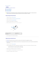
Replacing the Back I/O Panel
 |
View all Dell Studio One 19 1909 manuals
Add to My Manuals
Save this manual to your list of manuals |
Page 6 highlights
3. Flip the RF module and align the screw hole on the RF module with the screw hole on the chassis. 4. Replace the screw that secures the RF module. 5. Replace the optical drive (see Replacing the Optical Drive). 6. Replace the right speaker (see Replacing the Right Speaker). 7. Replace the processor fan (see Replacing the Processor Fan). 8. Replace the back I/O panel (see Replacing the Back I/O Panel). 9. Replace the stand (see Replacing the Stand). 10. Replace the shield (see Replacing the Shield). 11. Replace the computer cover (see Replacing the Computer Cover). Back to Contents Page
-
 1
1 -
 2
2 -
 3
3 -
 4
4 -
 5
5 -
 6
6 -
 7
7 -
 8
8 -
 9
9 -
 10
10 -
 11
11 -
 12
12 -
13
-
14
-
15
-
16
-
17
-
18
-
19
-
20
-
21
-
22
-
23
-
24
-
25
-
26
-
27
-
28
-
29
-
30
-
31
-
32
-
33
-
34
-
35
-
36
-
37
-
38
-
39
-
40
-
41
-
42
-
43
-
44
-
45
-
46
-
47
-
48
-
49
-
50
-
51
-
52
-
53
 |
 |

3.
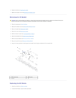
Flip the RF module and align the screw hole on the RF module with the screw hole on the chassis.
4.
Replace the screw that secures the RF module.
5.
Replace the optical drive (see
Replacing the Optical Drive
).
6.
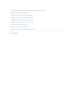
Replace the right speaker (see
Replacing the Right Speaker
).
7.
Replace the processor fan (see
Replacing the Processor Fan
).
8.
Replace the back I/O panel (see
Replacing the Back I/O Panel
).
9.
Replace the stand (see
Replacing the Stand
).
10.
Replace the shield (see
Replacing the Shield
).
11.
Replace the computer cover (see
Replacing the Computer Cover
).
Back to Contents Page