Dell XPS M1330 Owner's Manual - Page 137
Memory, Removing the DIMM 1 Memory Module
 |
UPC - 883585946433
View all Dell XPS M1330 manuals
Add to My Manuals
Save this manual to your list of manuals |
Page 137 highlights
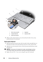
Memory CAUTION: Before you begin any of the procedures in this section, follow the safety instructions in the Product Information Guide. You can increase your computer memory by installing memory modules on the system board. See "Specifications" on page 165 for information on the memory supported by your computer. Install only memory modules that are intended for your computer. NOTE: Memory modules purchased from Dell are covered under your computer warranty. Your computer has two user-accessible SODIMM sockets that can be accessed from the bottom of the computer. NOTICE: If you need to install memory modules in two connectors, install a memory module in the connector labeled "DIMM1" before you install a module in the connector labeled "DIMM2." Removing the DIMM 1 Memory Module NOTICE: To avoid electrostatic discharge, ground yourself by using a wrist grounding strap or by periodically touching an unpainted metal surface (such as a connector on the back of the computer). NOTICE: If there is a memory module in DIMM 2, remove it prior to removing the memory module from DIMM 1. Failure to do so could result in damage to both memory modules. 1 Follow the procedures in "Before You Begin" on page 127. 2 Turn the computer over and loosen the three captive screws and the M2.5 x 5-mm screw. Remove the module cover. Adding and Replacing Parts 137
-
 1
1 -
2
-
3
-
4
-
5
-
6
-
7
-
8
-
9
-
10
-
11
-
12
-
13
-
14
-
15
-
16
-
17
-
18
-
19
-
20
-
21
-
22
-
23
-
24
-
25
-
26
-
27
-
28
-
29
-
30
-
31
-
32
-
33
-
34
-
35
-
36
-
37
-
38
-
39
-
40
-
41
-
42
-
43
-
44
-
45
-
46
-
47
-
48
-
49
-
50
-
51
-
52
-
53
-
54
-
55
-
56
-
57
-
58
-
59
-
60
-
61
-
62
-
63
-
64
-
65
-
66
-
67
-
68
-
69
-
70
-
71
-
72
-
73
-
74
-
75
-
76
-
77
-
78
-
79
-
80
-
81
-
82
-
83
-
84
-
85
-
86
-
87
-
88
-
89
-
90
-
91
-
92
-
93
-
94
-
95
-
96
-
97
-
98
-
99
-
100
-
101
-
102
-
103
-
104
-
105
-
106
-
107
-
108
-
109
-
110
-
111
-
112
-
113
-
114
-
115
-
116
-
117
-
118
-
119
-
120
-
121
-
122
-
123
-
124
-
125
-
126
-
127
-
128
-
129
-
130
-
131
-
 132
132 -
 133
133 -
 134
134 -
 135
135 -
 136
136 -
 137
137 -
 138
138 -
 139
139 -
 140
140 -
 141
141 -
 142
142 -
143
-
144
-
145
-
146
-
147
-
148
-
149
-
150
-
151
-
152
-
153
-
154
-
155
-
156
-
157
-
158
-
159
-
160
-
161
-
162
-
163
-
164
-
165
-
166
-
167
-
168
-
169
-
170
-
171
-
172
-
173
-
174
-
175
-
176
-
177
-
178
-
179
-
180
-
181
-
182
-
183
-
184
-
185
-
186
-
187
-
188
-
189
-
190
-
191
-
192
-
193
-
194
-
195
-
196
-
197
-
198
-
199
-
200
-
201
-
202
 |
 |
