Denon AVR-985S Owners Manual - Page 16
Display - 7 1 channel receiver
 |
UPC - 081757506106
View all Denon AVR-985S manuals
Add to My Manuals
Save this manual to your list of manuals |
Page 16 highlights
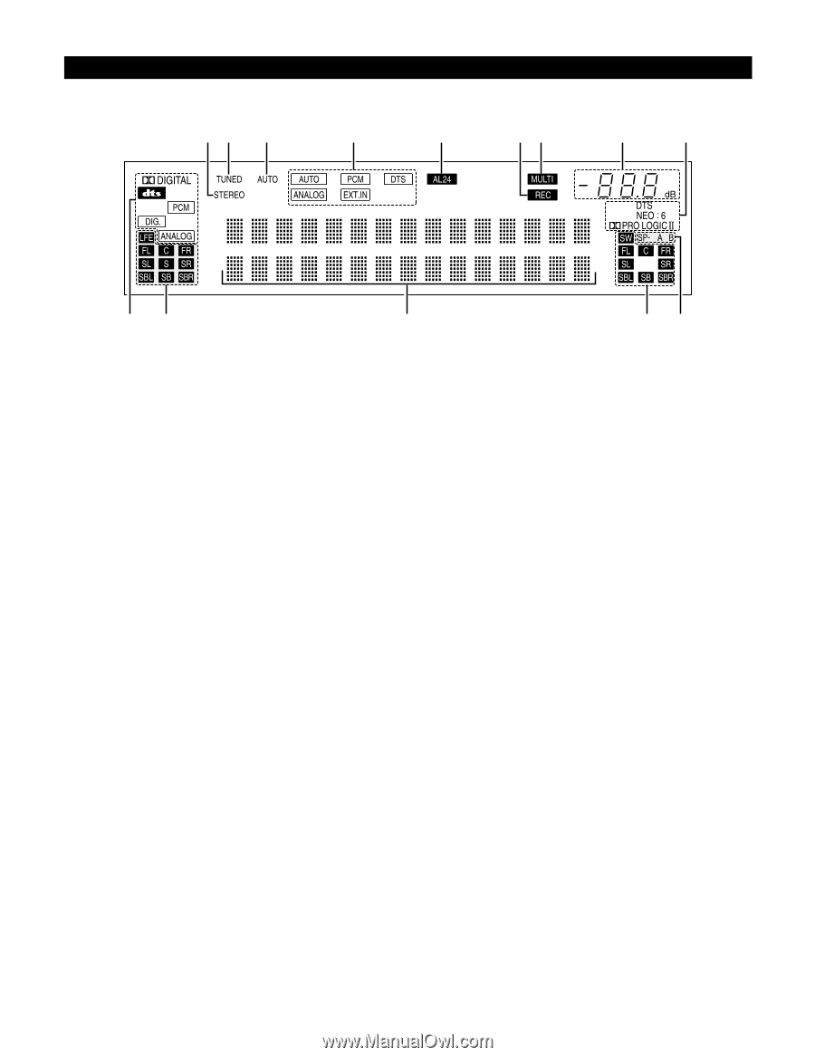
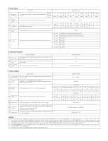
Display !4!3 !2 !1 !0 oi uy qw e rt q INPUT SIGNAL indicator The respective indicator will light corresponding to the input signal. w INPUT SIGNAL CHANNEL indicator The channels included in the input source will light. This displays bitstream signal channel. This does not light when signals are being input to the ANALOG, EXT.IN or PCM connectors. e Information display This displays the surround mode, function name or setting value, etc. r OUTPUT SIGNAL CHANNEL indicator The audio channels output from this unit will light. t SPEAKER indicator This lights corresponding to the settings of the front speakers. y Decoder indicator This lights when each decoder is operating. u MASTER VOLUME indicator This displays the volume level. The Setup item number is displayed in System Setup. i MULTI(ZONE) indicator ZONE2 mode is selected in ZONE2/REC SELECT. o REC OUT SOURCE indicator. REC OUT mode is selected in ZONE2/REC SELECT. !0 AL24 indicator The AL24 indicator lights when the PURE DIRECT, DIRECT and STEREO mode is selected in the PCM input signal. !1 INPUT MODE indicator This lights corresponding to the setting of the INPUT mode. !2 AUTO indicator This lights when the broadcast station is selected in the AUTO tuning mode. !3 TUNED indicator This lights when an FM/AM broadcast has been received. !4 STEREO indicator This lights when an FM stereo broadcast has been received. 16
-
 1
1 -
2
-
3
-
4
-
5
-
6
-
7
-
8
-
9
-
10
-
 11
11 -
 12
12 -
 13
13 -
 14
14 -
 15
15 -
 16
16 -
 17
17 -
 18
18 -
 19
19 -
 20
20 -
 21
21 -
22
-
23
-
24
-
25
-
26
-
27
-
28
-
29
-
30
-
31
-
32
-
33
-
34
-
35
-
36
-
37
-
38
-
39
-
40
-
41
-
42
-
43
-
44
-
45
-
46
-
47
-
48
-
49
-
50
-
51
-
52
-
53
-
54
-
55
-
56
-
57
-
58
-
59
-
60
-
61
-
62
-
63
-
64
-
65
-
66
-
67
-
68
-
69
-
70
-
71
-
72
-
73
-
74
-
75
-
76
-
77
-
78
-
79
-
80
-
81
-
82
-
83
-
84
-
85
-
86
-
87
-
88
-
89
-
90
-
91
-
92
-
93
-
94
-
95
-
96
-
97
-
98
-
99
-
100
 |
 |