Denon AVR-985S Owners Manual - Page 47
After completing system setup - avr 985 remote
 |
UPC - 081757506106
View all Denon AVR-985S manuals
Add to My Manuals
Save this manual to your list of manuals |
Page 47 highlights
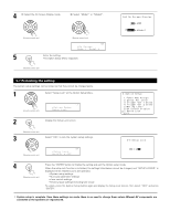
After completing system setup This button can be pressed at any time during the system setup process to complete the process. 1 Press the SYSTEM SETUP button at the System Setup Menu. The changed settings are entered and the on-screen display turns off. (Remote control unit) • On-screen display signals Signals input to the AVR-2805/985 On-screen display signal output VIDEO signal input jack (yellow) S-video signal input jack Video signal output to VIDEO MONITOR OUT jack (yellow) Video signal output to SVideo MONITOR OUT jack Video signal output to Color Difference (Component) Video MONITOR OUT jack 1 E E C C C 2 C E C C C 3 E C C C C 4 C C E C C (C: Signal E: No signal) (C: On-screen signals output E: On-screen signals not output) NOTE: • When a component video signal is input and when the "Video Input Mode" is set to the component fixed mode at Input setup, the on-screen display is only displayed when the System Setup, Surround Parameters and On Screen buttons are operated. 47
-
 1
1 -
2
-
3
-
4
-
5
-
6
-
7
-
8
-
9
-
10
-
11
-
12
-
13
-
14
-
15
-
16
-
17
-
18
-
19
-
20
-
21
-
22
-
23
-
24
-
25
-
26
-
27
-
28
-
29
-
30
-
31
-
32
-
33
-
34
-
35
-
36
-
37
-
38
-
39
-
40
-
41
-
 42
42 -
 43
43 -
 44
44 -
 45
45 -
 46
46 -
 47
47 -
 48
48 -
 49
49 -
 50
50 -
 51
51 -
 52
52 -
53
-
54
-
55
-
56
-
57
-
58
-
59
-
60
-
61
-
62
-
63
-
64
-
65
-
66
-
67
-
68
-
69
-
70
-
71
-
72
-
73
-
74
-
75
-
76
-
77
-
78
-
79
-
80
-
81
-
82
-
83
-
84
-
85
-
86
-
87
-
88
-
89
-
90
-
91
-
92
-
93
-
94
-
95
-
96
-
97
-
98
-
99
-
100
 |
 |