Dewalt D28140 Instruction Manual - Page 15
Switches, OPERATION, Guards and Flanges
 |
View all Dewalt D28140 manuals
Add to My Manuals
Save this manual to your list of manuals |
Page 15 highlights
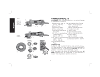
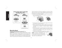
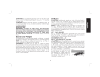
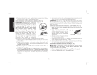
English CAUTION: Do not tighten the adjusting screw with the clamp lever in open position. Undetectable damage to the guard or the mounting hub may result. CAUTION: If guard cannot be tightened by adjusting clamp, do not use tool and take the tool and guard to a service center to repair or replace the guard. OPERATION WARNING: To reduce the risk of injury, turn unit off and disconnect it from power source before installing and removing accessories, before adjusting or when making repairs. Before reconnecting the tool, depress and release the trigger switch to ensure that the tool is off. An accidental start-up can cause injury. Guards and Flanges It is important to choose the correct guards and flanges to use with the grinder accessories. See pages 10-12 for the correct accessories. NOTE: Edge grinding and cutting can be performed with Type 27 wheels designed and specified for this purpose. WARNING: Accessories must be rated for at least the speed recommended on the tool warning label. Wheels and other accessories running over rated accessory speed may burst and cause injury. Every unthreaded accessory must have a 7/8" (22.2 mm) arbor hole. If it does not, it may have been designed for a circular saw and should not be used. Use only the accessories shown on pages 10-12. Accessory ratings must be above listed minimum wheel speed as shown on tool nameplate. Switches CAUTION: Hold the side handle and body of the tool firmly to maintain control of the tool at start up and during use and until the wheel or accessory stops rotating. Make sure the wheel has come to a complete stop before laying the tool down. NOTE: To reduce unexpected tool movement, do not switch the tool on or off while under load conditions. Allow the grinder to run up to full speed before touching the work surface. Lift the tool from the surface before turning the tool off. Allow the tool to stop rotating before putting it down. SOFT START FEATURE The soft start feature allows a slow speed build-up to avoid an initial jerk when starting. This feature is particularly useful when working in confined areas. Current surge will also be reduced. PADDLE SWITCH (FIG. 1, 5) D28114, D28114N, D28144, D28144N CAUTION: Before connecting the tool to a power source depress and release the paddle switch (A) once without depressing the lock- on button (Fig. 1, J) [D28114, D28144 only] to ensure that the switch is off. Depress and release the paddle switch as described above after any interruption in power supply to the tool, such as the activation of a ground fault interrupter, throwing of a circuit breaker, accidental unplugging, or power failure. To turn the tool on, push the lock-off FIG. 5 lever (B) toward the back of the tool, then depress the paddle switch (A). The tool will run while the switch is depressed. Turn the tool off by A releasing the paddle switch. B 13
-
 1
1 -
2
-
3
-
4
-
5
-
6
-
7
-
8
-
9
-
 10
10 -
 11
11 -
 12
12 -
 13
13 -
 14
14 -
 15
15 -
 16
16 -
 17
17 -
 18
18 -
 19
19 -
 20
20 -
21
-
22
-
23
-
24
-
25
-
26
-
27
-
28
-
29
-
30
-
31
-
32
-
33
-
34
-
35
-
36
-
37
-
38
-
39
-
40
-
41
-
42
-
43
-
44
-
45
-
46
-
47
-
48
-
49
-
50
-
51
-
52
-
53
-
54
-
55
-
56
-
57
-
58
-
59
-
60
-
61
-
62
-
63
-
64
-
65
-
66
-
67
-
68
-
69
-
70
-
71
-
72
-
73
-
74
-
75
-
76
 |
 |
