Dewalt D28140 Instruction Manual - Page 20
Mounting and Using Cutting, Type 1 Wheels Fig. 1
 |
View all Dewalt D28140 manuals
Add to My Manuals
Save this manual to your list of manuals |
Page 20 highlights
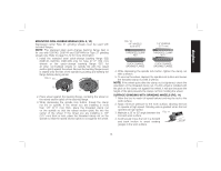
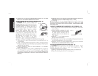
English USING WIRE CUP BRUSHES AND WIRE WHEELS (FIG. 16, 17) Wire wheels and brushes can be used for removing rust, scale and paint, and for smoothing irregular surfaces. 1. Allow the tool to reach full speed before touching the tool to the work surface. 2. Apply minimum pressure to work FIG. 16 surface, allowing the tool to operate at high speed. Material removal rate is greatest when the tool operates at high speed. 3. Maintain a 5˚ to 10˚ angle between 5˚-10˚ the tool and work surface for wire cup brushes. 4. Maintain contact between the edge of the wheel and the work surface with wire wheels. 5. Continuously move the tool in a forward and FIG. 17 backward motion to avoid creating gouges in the work surface. Allowing the tool to rest on the work surface without moving, or moving the tool in a circular motion causes burning and swirling marks on the work surface. 6. Remove the tool from the work surface before turning the tool off. Allow the tool to stop rotating before setting it down. CAUTION: Use extra care when working over an edge, as a sudden sharp movement of grinder may be experienced. Mounting and Using Cutting (Type 1) Wheels (Fig. 1) Cutting wheels include diamond wheels and abrasive discs. Abrasive cutting wheels for metal and concrete use are available. Diamond blades for concrete cutting can also be used. NOTE: All grinders that use Type 1 wheels use the quick-change backing flange (G1). WARNING: A closed, 2-sided cutting wheel guard is not included with this tool (D28140, D28144, D28144N ONLY) and is required when using cutting wheels. Failure to use proper flange and guard can result in injury resulting from wheel breakage and wheel contact. See page 10 for more information. MOUNTING CLOSED (TYPE 1) GUARD (FIG. 18, 19) 1. Open the guard latch (M). Align the lugs (N) on the guard with the slots (O) on the gear case. FIG. 18 O N M I 2. Push the guard down until the guard lug engages and rotates freely in the groove on the gear case hub. 18
-
 1
1 -
2
-
3
-
4
-
5
-
6
-
7
-
8
-
9
-
10
-
11
-
12
-
13
-
14
-
 15
15 -
 16
16 -
 17
17 -
 18
18 -
 19
19 -
 20
20 -
 21
21 -
 22
22 -
 23
23 -
 24
24 -
 25
25 -
26
-
27
-
28
-
29
-
30
-
31
-
32
-
33
-
34
-
35
-
36
-
37
-
38
-
39
-
40
-
41
-
42
-
43
-
44
-
45
-
46
-
47
-
48
-
49
-
50
-
51
-
52
-
53
-
54
-
55
-
56
-
57
-
58
-
59
-
60
-
61
-
62
-
63
-
64
-
65
-
66
-
67
-
68
-
69
-
70
-
71
-
72
-
73
-
74
-
75
-
76
 |
 |
