Dewalt D28140 Instruction Manual - Page 16
Mounting and Using Depressed Center, Grinding Wheels and Sanding Flap Discs
 |
View all Dewalt D28140 manuals
Add to My Manuals
Save this manual to your list of manuals |
Page 16 highlights
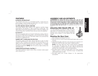
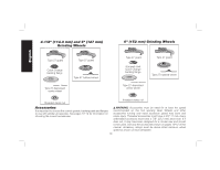
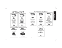
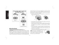
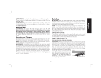
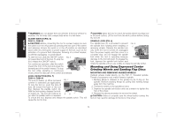
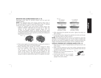
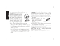
English WARNING: Do not disable the lock-off lever. If the lock-off lever is disabled, the tool may start unexpectedly when it is laid down. SLIDER SWITCH (FIG. 6) D28131, D28140 CAUTION: Before connecting the tool to a power supply, be sure the switch is in the off position by pressing the rear part of the switch and releasing. Ensure the switch is in the off position as described above after any interruption in power supply to the tool, such as the activation of a ground fault interrupter, throwing of a circuit breaker, accidental unplugging, or power failure. To start the tool, slide the ON/OFF switch FIG. 6 (L) toward the front of the tool. To stop the tool, release the ON/OFF switch. For continuous operation, slide the switch toward the front of the tool and press the forward part of the switch inward. To stop L the tool while operating in continuous mode, press the rear part of the switch and release. LOCK-ON BUTTON (FIG. 7) D28114, D28144 The lock-on button (J) offers increased FIG. 7 comfort in extended use applications. To lock the tool on, push the lock-off lever (B) toward the back of the tool then depress the paddle switch (A). With the tool running, depress the lockon button (J). The tool will continue to A B J run after the paddle switch is released. To unlock the tool, depress and release the paddle switch. This will cause the tool to stop. CAUTION: Allow the tool to reach full speed before touching tool to the work surface. Lift the tool from the work surface before turning the tool off. SPINDLE LOCK (FIG. 8) The spindle lock (C) is provided to prevent FIG. 8 the spindle from rotating when installing or C removing wheels. Operate the spindle lock only when the tool is turned off, unplugged from the power supply, and has come to a complete stop. Do not engage the spindle lock while the tool is operating because damage to the tool will result. To engage the lock, depress the spindle lock button and rotate the spindle until you are unable to rotate the spindle further. Mounting and Using Depressed Center Grinding Wheels and Sanding Flap Discs MOUNTING AND REMOVING HUBBED WHEELS Hubbed wheels install directly on the 5/8"-11 threaded spindle. Thread of accessory must match thread of spindle. 1. Backing flange is retained to the grinder by an O-ring on the spindle. Remove backing flange by pulling and twisting flange away form the machine. 2. Thread the wheel on the spindle by hand. 3. Depress the spindle lock button and use a wrench to tighten the hub of the wheel. 4. Reverse the above procedure to remove the wheel. CAUTION: Failure to properly seat the wheel before turning the tool on may result in damage to the tool or the wheel. 14
-
 1
1 -
2
-
3
-
4
-
5
-
6
-
7
-
8
-
9
-
10
-
 11
11 -
 12
12 -
 13
13 -
 14
14 -
 15
15 -
 16
16 -
 17
17 -
 18
18 -
 19
19 -
 20
20 -
 21
21 -
22
-
23
-
24
-
25
-
26
-
27
-
28
-
29
-
30
-
31
-
32
-
33
-
34
-
35
-
36
-
37
-
38
-
39
-
40
-
41
-
42
-
43
-
44
-
45
-
46
-
47
-
48
-
49
-
50
-
51
-
52
-
53
-
54
-
55
-
56
-
57
-
58
-
59
-
60
-
61
-
62
-
63
-
64
-
65
-
66
-
67
-
68
-
69
-
70
-
71
-
72
-
73
-
74
-
75
-
76
 |
 |
