Dewalt D28140 Instruction Manual - Page 17
D28140, D28144, D28144N only for Type 27 6 152 mm
 |
View all Dewalt D28140 manuals
Add to My Manuals
Save this manual to your list of manuals |
Page 17 highlights
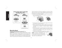
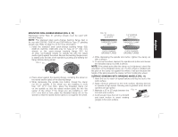
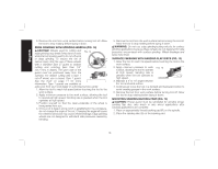
English MOUNTING NON-HUBBED WHEELS (FIG. 9, 10) Depressed center Type 27 grinding wheels must be used with included flanges. NOTE: The stamped steel quick-change backing flange (G2) is for use with D28140, D28144 and D28144N for Type 27 grinding wheels only. Refer to page 10-12 for more information. 1. Install the stamped steel quick-change backing flange (G2) (D28140, D28144, D28144N only) for Type 27 6" (152 mm) wheels or the quick-change backing flange (G1) for all other non-hubbed wheels on spindle (Q) with the raised section (pilot) against the wheel. Be sure the backing flange recess is seated onto the flats of the spindle by pushing and twisting the flange before placing wheel. FIG. 9 G1 Q H 2. Place wheel against the backing flange, centering the wheel on the raised section (pilot) of the backing flange. 3. While depressing the spindle lock button, thread the clamp nut (H) on spindle. If the wheel you are installing is more than 1/8" (3.17 mm) thick, place the threaded clamp nut on the spindle so that the raised section (pilot) fits into the center of the wheel. If the wheel you are installing is 1/8" (3.17 mm) thick or less, place the threaded clamp nut on the spindle so that the raised section (pilot) is not against the wheel. FIG. 10 1/4" WHEELS (6.35 mm) THREADED CLAMP NUT 1/8" WHEELS (3.17 mm) THREADED CLAMP NUT QUICK-CHANGE BACKING FLANGE QUICK-CHANGE BACKING FLANGE 4. While depressing the spindle lock button, tighten the clamp nut with a wrench. 5. To remove the wheel, depress the spindle lock button and loosen the threaded clamp nut with a wrench. NOTE: If the wheel spins after the clamp nut is tightened, check the orientation of the threaded clamp nut. If a thin wheel is installed with the pilot on the clamp nut against the wheel, it will spin because the height of the pilot prevents the clamp nut from holding the wheel. SURFACE GRINDING WITH GRINDING WHEELS (FIG. 11) 1. Allow the tool to reach full speed before touching the tool to the work surface. 2. Apply minimum pressure to the work surface, allowing the tool to operate at high speed. Grinding rate is greatest when the tool operates at high speed. 3. Maintain a 20˚ to 30˚ angle between the FIG. 11 tool and work surface. 4. Continuously move the tool in a forward and back motion to avoid creating 20˚-30˚ gouges in the work surface. 15
-
 1
1 -
2
-
3
-
4
-
5
-
6
-
7
-
8
-
9
-
10
-
11
-
 12
12 -
 13
13 -
 14
14 -
 15
15 -
 16
16 -
 17
17 -
 18
18 -
 19
19 -
 20
20 -
 21
21 -
 22
22 -
23
-
24
-
25
-
26
-
27
-
28
-
29
-
30
-
31
-
32
-
33
-
34
-
35
-
36
-
37
-
38
-
39
-
40
-
41
-
42
-
43
-
44
-
45
-
46
-
47
-
48
-
49
-
50
-
51
-
52
-
53
-
54
-
55
-
56
-
57
-
58
-
59
-
60
-
61
-
62
-
63
-
64
-
65
-
66
-
67
-
68
-
69
-
70
-
71
-
72
-
73
-
74
-
75
-
76
 |
 |
