Dewalt D28140 Instruction Manual - Page 21
Pmaintenance
 |
View all Dewalt D28140 manuals
Add to My Manuals
Save this manual to your list of manuals |
Page 21 highlights
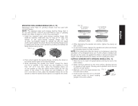
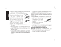
English 3. Rotate guard (I) into desired working position. The guard body should be positioned between the spindle and the operator to provide maximum operator protection. 4. Close the guard latch to secure the guard on the gear case cover. You should be unable to rotate the guard by hand when the latch is in closed position. If rotation is possible, tighten the adjusting screw (P) with clamp lever in the closed position. Do not operate grinder with a loose guard or clamp lever in open position. 5. To remove the guard, open the guard latch, rotate the guard so that the arrows are aligned and pull up on the guard. NOTE: If, after a period of time, the guard FIG. 19 becomes loose, tighten the adjusting screw (P) with the clamp lever in the closed position. P CAUTION: Do not tighten adjusting screw with clamp lever in open position. Undetectable damage to guard or mounting hub may result. MOUNTING CUTTING WHEELS CAUTION: Matching diameter backing flange and threaded clamp nut (included with tool) must be used for cutting wheels. 1. Place the unthreaded backing flange on spindle with the raised section (pilot) facing up. The raised section (pilot) on the backing flange will be against the wheel when the wheel is installed. 2. Place the wheel on the quick-change backing flange, centering the wheel on the raised section (pilot). 3. Install the threaded clamp nut with the raised section (pilot) facing away from the wheel. 4. Depress the spindle lock button and tighten clamp nut with a wrench. 5. To remove the wheel, grasp and turn while depressing the spindle lock button. USING CUTTING WHEELS (FIG. 20) WARNING: Do not use edge grinding/ cutting FIG. 20 wheels for surface grinding applications because these wheels are not designed for side pressures encountered with surface grinding. Wheel breakage and injury may result. 1. Allow tool to reach full speed before touching tool to work surface. 2. Apply minimum pressure to work surface, allowing tool to operate at high speed. Cutting rate is greatest when the tool operates at high speed. 3. Once a cut is begun and a notch is established in the workpiece, do not change the angle of the cut. Changing the angle will cause the wheel to bend and may cause wheel breakage. 4. Remove the tool from work surface before turning tool off. Allow the tool to stop rotating before setting it down. MAINTENANCE WARNING: To reduce the risk of injury, turn unit off and disconnect it from power source before installing and removing accessories, before adjusting or when making repairs. Before reconnecting the tool, depress and release the trigger switch to ensure that the tool is off. An accidental startup can cause injury. 19
-
 1
1 -
2
-
3
-
4
-
5
-
6
-
7
-
8
-
9
-
10
-
11
-
12
-
13
-
14
-
15
-
 16
16 -
 17
17 -
 18
18 -
 19
19 -
 20
20 -
 21
21 -
 22
22 -
 23
23 -
 24
24 -
 25
25 -
 26
26 -
27
-
28
-
29
-
30
-
31
-
32
-
33
-
34
-
35
-
36
-
37
-
38
-
39
-
40
-
41
-
42
-
43
-
44
-
45
-
46
-
47
-
48
-
49
-
50
-
51
-
52
-
53
-
54
-
55
-
56
-
57
-
58
-
59
-
60
-
61
-
62
-
63
-
64
-
65
-
66
-
67
-
68
-
69
-
70
-
71
-
72
-
73
-
74
-
75
-
76
 |
 |
