Dewalt DW723 Instruction Manual - Page 5
DW723 MOUNTING PROCEDURE CHART, Left Side, Right Side - mounting bracket
 |
View all Dewalt DW723 manuals
Add to My Manuals
Save this manual to your list of manuals |
Page 5 highlights
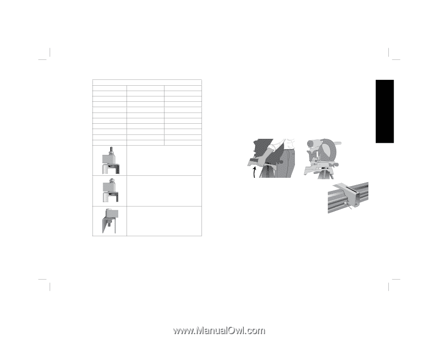
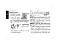
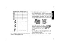
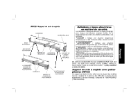
English DW723 MOUNTING PROCEDURE CHART Left Side Right Side DW703 1 1 DW705 1 1 DW706 1 1 DW708 1 2 DW712 1 2 DW713 1 1 DW715 1 1 DW716 1 1 DW717 2 1 DW718 3 2 1 = Long screw, Head on bottom 5. Repeat procedure on the other end of the bracket. 6. Move the 2 x 4 to the other side of the saw to hold the other end of the saw up in order to access the saw base. 7. Feed carriage bolts through the other bracket and the base of the saw as before. Ensure both brackets are parallel to each other. 8. To place the saw onto the stand, grasp and lift saw by mounting bracket assembly by the release levers. These levers do not lock the saw laterally in place but merely serve as a means of mounting the saw to the beam. 2 = Short screw, Head on bottom 3 = Long screw, Head on top 4. Once the carriage bolt (hardware bag) is installed per Mounting Procedure Chart, assemble a flat washer; lock washer and nut onto the bolt. Tighten the bolts finger tight. 9. Approach the beam with saw/bracket assembly tilting toward your body slightly. Engage the concave front lip of the mounting bracket with rounded edge of beam. One of the brackets must engage the locator clip (G) to prohibit lateral movement of the saw G during use. 10. When front edge of the beam and locking locator clip are engaged, a slight downward pivot will allow secure engagement of the rear levers to back of beam. Rock the saw gently on the brackets to verify locking in position. 11. Adjust the saw position as necessary to have the blade perpendicular to the beam when in the 0 degree miter position. 12. Tighten the four nuts holding the saw to the brackets securely. 3
-
 1
1 -
 2
2 -
 3
3 -
 4
4 -
 5
5 -
 6
6 -
 7
7 -
 8
8 -
 9
9 -
 10
10 -
 11
11 -
12
-
13
-
14
-
15
-
16
-
17
-
18
-
19
-
20
-
21
-
22
-
23
-
24
 |
 |