Dewalt DWE4517 Instruction Manual - Page 10
COMPONENTS FIG. 1, Features, Accessories and Attachments
 |
View all Dewalt DWE4517 manuals
Add to My Manuals
Save this manual to your list of manuals |
Page 10 highlights
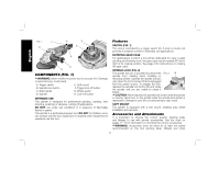
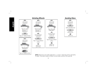
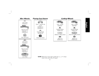
English FIG. 1 F B H D E A C G COMPONENTS (FIG. 1) WARNING: Never modify the power tool or any part of it. Damage or personal injury could result. A. Trigger switch B. Spindle lock button C. Side handle D. Spindle E. Soft mount F. Trigger lock off button G. Wheel guard H. Lock-on button INTENDED USE This grinder is designed for professional grinding, sanding, wire brushing, polishing or abrasive, cutting-off applications. DO NOT use under wet conditions or in presence of flammable liquids or gases. This grinder is a professional power tool. DO NOT let children come into contact with the tool. Supervision is required when inexperienced operators use this tool. Features SWITCH (FIG. 1) This tool is controlled by a trigger switch (A). A lock-on button (H) provides increased comfort in extended use applications. ROTATING GEAR CASE For applications in which a tool will be dedicated for uses in edge grinding and finishing work, the gear case may be rotated 90° left or right of its original position. See page 9 for instructions on rotating the gear case. SPINDLE LOCK (FIG. 2) The spindle lock pin is provided to prevent the FIG. 2 B spindle from rotating when installing or removing wheels. Operate the spindle lock pin only when the tool is turned off and unplugged from the power source. To engage the lock, depress the spindle lock button (B) and rotate the spindle until you are unable to rotate it further. CAUTION: Never depress the spindle lock button while the grinder is running. Never turn on the grinder while the spindle lock button is depressed. Damage to your tool or personal injury may result. SOFT MOUNT The grinder is equipped with a soft mount, enabling easy wheel installation and removal. Accessories and Attachments It is important to choose the correct guards, backing pads and flanges to use with grinder accessories. See the chart on pages 11-13 for information on choosing the correct accessories. WARNING: Accessories must be rated for at least the speed recommended on the tool warning label. Wheels and other 8
-
 1
1 -
2
-
3
-
4
-
 5
5 -
 6
6 -
 7
7 -
 8
8 -
 9
9 -
 10
10 -
 11
11 -
 12
12 -
 13
13 -
 14
14 -
 15
15 -
16
-
17
-
18
-
19
-
20
-
21
-
22
-
23
-
24
-
25
-
26
-
27
-
28
-
29
-
30
-
31
-
32
-
33
-
34
-
35
-
36
-
37
-
38
-
39
-
40
-
41
-
42
-
43
-
44
-
45
-
46
-
47
-
48
-
49
-
50
-
51
-
52
-
53
-
54
-
55
-
56
-
57
-
58
-
59
-
60
-
61
-
62
-
63
-
64
-
65
-
66
-
67
-
68
 |
 |
