EVGA 141-BL-E757-TR User Guide - Page 15
EVGA X58 SLI LE Motherboard Layout
 |
UPC - 843368010775
View all EVGA 141-BL-E757-TR manuals
Add to My Manuals
Save this manual to your list of manuals |
Page 15 highlights
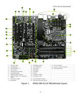
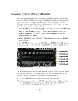
16 18 17 17 19 17 17 15 14 13 12 4 11 EVGA X58 SLI Motherboard 20 4 21 22 1 2 10 3 9 7 8 1. CPU Socket 1366 2. Intel X58 Chipset 3. DDR3 DIMM Slots 1 - 6 4. Fan Connectors 5. 24-Pin ATX Power Connector 6. Intel ICH10R Chipset 7. Serial-ATA (SATA) Connectors 8. Debug LED Display - CPU Temperature Monitor 9. Front Panel Connector 10. USB Headers 23 4 5 6 11. IEEE1394a Connector 12. Clear CMOS Button 13. Power Button 14. Reset Button 15. PC Speaker 16. PCI slot 17. PCI Express 2.0 Slots 18. PCI Express x1 Slot 19. Front Panel Audio Connector 20. Back Panel Connectors (Figure 2) 21. CPU Fan Connector 22. 8-pin ATX_12V Power Connector 23. Motherboard Battery Figure 1. EVGA X58 SLI LE Motherboard Layout 15
-
 1
1 -
2
-
3
-
4
-
5
-
6
-
7
-
8
-
9
-
 10
10 -
 11
11 -
 12
12 -
 13
13 -
 14
14 -
 15
15 -
 16
16 -
 17
17 -
 18
18 -
 19
19 -
 20
20 -
21
-
22
-
23
-
24
-
25
-
26
-
27
-
28
-
29
-
30
-
31
-
32
-
33
-
34
-
35
-
36
-
37
-
38
-
39
-
40
-
41
-
42
-
43
-
44
-
45
-
46
-
47
-
48
-
49
-
50
-
51
-
52
-
53
-
54
-
55
-
56
-
57
-
58
-
59
-
60
-
61
-
62
-
63
-
64
-
65
-
66
-
67
-
68
-
69
-
70
-
71
-
72
-
73
-
74
-
75
-
76
 |
 |

EVGA X58 SLI Motherboard
15
1.
CPU Socket 1366
11. IEEE1394a Connector
21. CPU Fan Connector
2.
Intel X58 Chipset
12. Clear CMOS Button
22. 8-pin ATX_12V Power Connector
3.
DDR3 DIMM Slots 1
–
6
13. Power Button
23. Motherboard Battery
4.
Fan Connectors
14. Reset Button
5.
24-Pin ATX Power Connector
15.
PC Speaker
6.
Intel ICH10R Chipset
16.
PCI slot
7.
Serial-ATA (SATA) Connectors
17. PCI Express 2.0 Slots
8.
Debug LED Display - CPU Temperature
Monitor
18. PCI Express x1 Slot
9.
Front Panel Connector
19.
Front Panel Audio Connector
10. USB Headers
20.
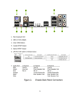
Back Panel Connectors (Figure 2)
Figure 1.
EVGA X58 SLI LE Motherboard Layout
1
6
4
5
9
17
16
18
17
20
17
12
21
19
2
7
8
3
23
10
4
11
13
14
15
17
22
4