Epson C107001 User Manual - Page 119
Interface Specifications, Specifications and Pin Assignments, Technical Specifications
 |
UPC - 010343157507
View all Epson C107001 manuals
Add to My Manuals
Save this manual to your list of manuals |
Page 119 highlights
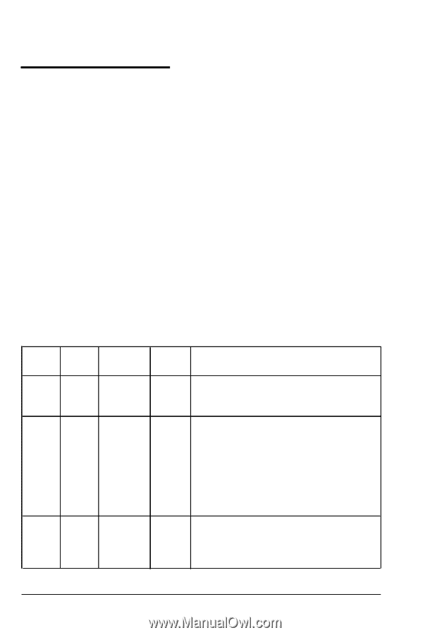
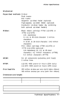
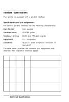
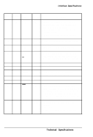
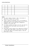
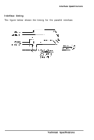
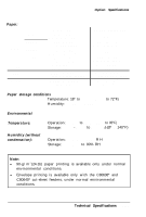
Interface Specifications Your printer is equipped with a parallel interface. Specifications and pin assignments The built-in parallel interface has the following characteristics: Data format: 8-bit parallel Synchronization: STROBE pulse Handshake timing: BUSY and ACKNLG signals Signal level: TTL compatible Connector: 36-pin 57-30360 Amphenol connector or equivalent The table below provides the connector pin assignments and describes their respective interface signals. Signal Return Pin Pin 1 19 2 20 3 21 4 22 5 23 6 24 7 25 8 26 9 27 10 28 Signal Direction Description STROBE DATA 1 DATA 2 DATA 3 DATA 4 DATA 5 DATA 6 DATA 7 DATA 8 ACKNLG IN IN IN IN IN IN IN IN IN OUT STROBE pulse to read data. Pulse width must be more than 0.5 microseconds at the receiving terminal. These signals represent information of the 1st to 8th bits of parallel data respectively. Each signal is at HIGH level when data is logical 1 and LOW when it is logical 0. About an 11 -microsecond pulse. LOW indicates that data has been received and that the printer is ready to accept more data. 7-10 Technical Specifications
-
 1
1 -
2
-
3
-
4
-
5
-
6
-
7
-
8
-
9
-
10
-
11
-
12
-
13
-
14
-
15
-
16
-
17
-
18
-
19
-
20
-
21
-
22
-
23
-
24
-
25
-
26
-
27
-
28
-
29
-
30
-
31
-
32
-
33
-
34
-
35
-
36
-
37
-
38
-
39
-
40
-
41
-
42
-
43
-
44
-
45
-
46
-
47
-
48
-
49
-
50
-
51
-
52
-
53
-
54
-
55
-
56
-
57
-
58
-
59
-
60
-
61
-
62
-
63
-
64
-
65
-
66
-
67
-
68
-
69
-
70
-
71
-
72
-
73
-
74
-
75
-
76
-
77
-
78
-
79
-
80
-
81
-
82
-
83
-
84
-
85
-
86
-
87
-
88
-
89
-
90
-
91
-
92
-
93
-
94
-
95
-
96
-
97
-
98
-
99
-
100
-
101
-
102
-
103
-
104
-
105
-
106
-
107
-
108
-
109
-
110
-
111
-
112
-
113
-
 114
114 -
 115
115 -
 116
116 -
 117
117 -
 118
118 -
 119
119 -
 120
120 -
 121
121 -
 122
122 -
 123
123 -
 124
124 -
125
-
126
-
127
-
128
-
129
-
130
-
131
-
132
-
133
-
134
-
135
-
136
-
137
-
138
-
139
-
140
-
141
-
142
-
143
-
144
-
145
-
146
-
147
-
148
-
149
-
150
-
151
-
152
-
153
 |
 |