Epson C107001 User Manual - Page 120
Signal Return, isolated from the logic ground.
 |
UPC - 010343157507
View all Epson C107001 manuals
Add to My Manuals
Save this manual to your list of manuals |
Page 120 highlights
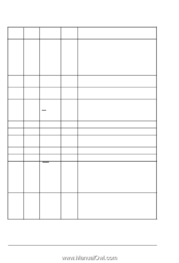
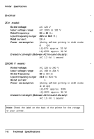
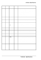
Interface Specifications Signal Return Pin Pin 11 29 Signal BUSY 12 30 PE 13 - SLCT 14 - AUTO FEED XT 15 - 16 - 17 - 18 - 19-30 - 31 16 NC GND CHASSIS GND NC GND INIT 32 - ERROR Direction Description OUT OUT OUT IN IN OUT A HIGH signal indicates that the printer cannot receive data. The signal goes HIGH in the following cases: 1) During data entry (ea. char. time) 2) During printing 3) When the PAUSE button is pressed 4) During an error state. A HIGH signal indicates that the printer is out of paper. Pulled up to 5 V through 3.3 Kohm resistance. When this signal is LOW, the paper is automatically fed one line after printing. (The signal level can be fixed to this by setting DIP switch 2-4 to on.) Not used. Logic ground level. Printer's chassis ground, which is isolated from the logic ground. Not used. Twisted-pair return signal ground level. When this level becomes LOW, the printer controller is reset to its power-up state and the print buffer is cleared. This level is normally HIGH; its pulse width must be more than 50 microseconds at the receiving terminal. This level becomes LOW when the printer is: 1) in a paper-out state 2) when the PAUSE button is pressed 3) in an error state. Technical Specifications 7-11
-
 1
1 -
2
-
3
-
4
-
5
-
6
-
7
-
8
-
9
-
10
-
11
-
12
-
13
-
14
-
15
-
16
-
17
-
18
-
19
-
20
-
21
-
22
-
23
-
24
-
25
-
26
-
27
-
28
-
29
-
30
-
31
-
32
-
33
-
34
-
35
-
36
-
37
-
38
-
39
-
40
-
41
-
42
-
43
-
44
-
45
-
46
-
47
-
48
-
49
-
50
-
51
-
52
-
53
-
54
-
55
-
56
-
57
-
58
-
59
-
60
-
61
-
62
-
63
-
64
-
65
-
66
-
67
-
68
-
69
-
70
-
71
-
72
-
73
-
74
-
75
-
76
-
77
-
78
-
79
-
80
-
81
-
82
-
83
-
84
-
85
-
86
-
87
-
88
-
89
-
90
-
91
-
92
-
93
-
94
-
95
-
96
-
97
-
98
-
99
-
100
-
101
-
102
-
103
-
104
-
105
-
106
-
107
-
108
-
109
-
110
-
111
-
112
-
113
-
114
-
 115
115 -
 116
116 -
 117
117 -
 118
118 -
 119
119 -
 120
120 -
 121
121 -
 122
122 -
 123
123 -
 124
124 -
 125
125 -
126
-
127
-
128
-
129
-
130
-
131
-
132
-
133
-
134
-
135
-
136
-
137
-
138
-
139
-
140
-
141
-
142
-
143
-
144
-
145
-
146
-
147
-
148
-
149
-
150
-
151
-
152
-
153
 |
 |