Epson C107001 User Manual - Page 121
twisted-pair cable for each signal and to complete the, connection on the return side.
 |
UPC - 010343157507
View all Epson C107001 manuals
Add to My Manuals
Save this manual to your list of manuals |
Page 121 highlights
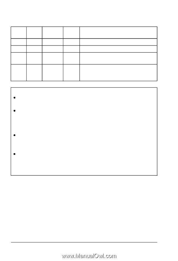
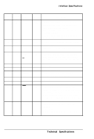
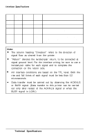
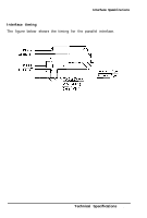
Interface Specifications Signal Return Pin Pin Signal Direction Description 33 - GND - Same as for pins 19-30. 34 - NC - Not used. 35 - - OUT Pulled up to 5 V through 3.3 Kohm resistance. 36 - SLCT IN IN The DC1/DCB code is valid only when this signal is HIGH. This signal is always LOW. Note: The column heading "Direction" refers to the direction of signal flow as viewed from the printer. "Return" denotes the twisted-pair return, to be connected at signal ground level. For the interface wiring, be sure to use a twisted-pair cable for each signal and to complete the connection on the return side. All interface conditions are based on the TTL level. Both the rise and fall times of each signal must be less than 0.2 microseconds. Data transfer must be carried out by observing the ACKNLG or BUSY signal. (Data transfer to this printer can be carried out only after receipt of the ACKNLG signal or when the BUSY signal is LOW.) 7-12 Technical Specifications
-
 1
1 -
2
-
3
-
4
-
5
-
6
-
7
-
8
-
9
-
10
-
11
-
12
-
13
-
14
-
15
-
16
-
17
-
18
-
19
-
20
-
21
-
22
-
23
-
24
-
25
-
26
-
27
-
28
-
29
-
30
-
31
-
32
-
33
-
34
-
35
-
36
-
37
-
38
-
39
-
40
-
41
-
42
-
43
-
44
-
45
-
46
-
47
-
48
-
49
-
50
-
51
-
52
-
53
-
54
-
55
-
56
-
57
-
58
-
59
-
60
-
61
-
62
-
63
-
64
-
65
-
66
-
67
-
68
-
69
-
70
-
71
-
72
-
73
-
74
-
75
-
76
-
77
-
78
-
79
-
80
-
81
-
82
-
83
-
84
-
85
-
86
-
87
-
88
-
89
-
90
-
91
-
92
-
93
-
94
-
95
-
96
-
97
-
98
-
99
-
100
-
101
-
102
-
103
-
104
-
105
-
106
-
107
-
108
-
109
-
110
-
111
-
112
-
113
-
114
-
115
-
 116
116 -
 117
117 -
 118
118 -
 119
119 -
 120
120 -
 121
121 -
 122
122 -
 123
123 -
 124
124 -
 125
125 -
 126
126 -
127
-
128
-
129
-
130
-
131
-
132
-
133
-
134
-
135
-
136
-
137
-
138
-
139
-
140
-
141
-
142
-
143
-
144
-
145
-
146
-
147
-
148
-
149
-
150
-
151
-
152
-
153
 |
 |