Epson Stylus COLOR 3000 Service Manual
Epson Stylus COLOR 3000 - Ink Jet Printer Manual
 |
View all Epson Stylus COLOR 3000 manuals
Add to My Manuals
Save this manual to your list of manuals |
Epson Stylus COLOR 3000 manual content summary:
- Epson Stylus COLOR 3000 | Service Manual - Page 1
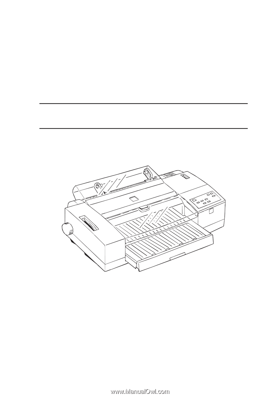
EPSON COLOR INK JET PRINTER EPSON Stylus COLOR 3000 SERVICE MANUAL SEIKO EPSON CORPORATION 4007664 - Epson Stylus COLOR 3000 | Service Manual - Page 2
NOTICE All rights reserved. Reproduction of any part of this manual in any form whatsoever without SEIKO EPSON's express written permission is forbidden. The contents of this manual are subjects to change without notice. All efforts have been made to ensure the accuracy of the contents of this - Epson Stylus COLOR 3000 | Service Manual - Page 3
in performing procedures preceded by WARNING Headings. Signals a precaution which, if MANUAL. DO NOT CONNECT THE UNIT TO A POWER SOURCE UNTIL INSTRUCTED TO DO SO. WHEN THE POWER SUPPLY CABLE THE EPSON PRODUCT HAS BEEN DISCONNECTED FROM THE POWER SOURCE BEFORE REMOVING OR REPLACING PRINTED CIRCUIT - Epson Stylus COLOR 3000 | Service Manual - Page 4
PREFACE This manual describes functions, theory of electrical and mechanical operations, maintenance, and repair of Stylus COLOR 3000. The instructions and procedures included herein are intended for the experience repair technician, and attention should be given to the precautions on the preceding - Epson Stylus COLOR 3000 | Service Manual - Page 5
- Epson Stylus COLOR 3000 | Service Manual - Page 6
TABLE OF CONTENTS CHAPTER 1. CHAPTER 2. CHAPTER 3. CHAPTER 4. CHAPTER 5. CHAPTER 6. APPENDIX GENERAL DESCRIPTION OPERATING PRINCIPLES DISASSEMBLY AND ASSEMBLY ADJUSTMENT TROUBLESHOOTING MAINTENANCE vi - Epson Stylus COLOR 3000 | Service Manual - Page 7
1.4 Interfaces...1-16 1.4.1 Parallel Interface ...1-16 1.4.2 Mac Serial Interface...1-20 1.4.3 Optional Interface ...1-21 1.4.4 Printer Adjustment Mode...1-29 1.5.4 Printer Initialization ...1-30 1.5.5 Self-test Printing Mode ...1-30 1.5.6 Hexadecimal Dump Function 1-30 1.5.7 Monochrome Printing - Epson Stylus COLOR 3000 | Service Manual - Page 8
The EPSON Stylus COLOR 3000 is a high-performance color ink jet printer designed for the office market as well as for plotter use with a wide paper availability up to full A2 size. The main features of this printer are: Paper availability in wide range A-2 (ANSI C-size) paper supported Printable - Epson Stylus COLOR 3000 | Service Manual - Page 9
interface cable C83605∗/C83606∗ from D-SUB 9-pin (computer) to D-SUB 25-pin (printer) C81101∗ Banner paper holder with cutting guide (Banner Paper Kit) Ink Cartridges S020118 Black ink cartridge S020122 Yellow ink cartridge S020126 Magenta ink cartridge S020130 Cyan ink cartridge EPSON - Epson Stylus COLOR 3000 | Service Manual - Page 10
EPSON Stylus COLOR 3000 Table 1-2. Options and Consumables (continued) Model Description S041071 EPSON photo quality glossy film (A4) S041072 EPSON photo quality glossy film (Letter) S041107 EPSON photo quality glossy film (A6) S041073 S041075 EPSON photo quality glossy film (A3) EPSON - Epson Stylus COLOR 3000 | Service Manual - Page 11
information on the EPSON Stylus COLOR 3000. 1.3.1 Printing Specifications Print method Nozzle configuration On demand Ink jet Monochrome Color (magenta, cyan, yellow) 128 nozzles (32 x 4 staggered) 64 nozzles (32 x 4 staggered, each color) Figure 1-2. Nozzle Configuration Print direction Bi - Epson Stylus COLOR 3000 | Service Manual - Page 12
EPSON Stylus COLOR 3000 1.3.2 Control codes ESCP/2 and expanded raster graphics code EPSON Remote command IBM XL24E Estonia ISO 8859-2 (ISO Latin 2) PC 866 LAT Typeface Bit map LQ font EPSON Roman EPSON Sans Serif EPSON Courier EPSON Prestige EPSON Script 10 cpi, 12 cpi, 15 cpi, Proportional 10 - Epson Stylus COLOR 3000 | Service Manual - Page 13
paper Feeding speed Bitmap Fonts EPSON Roman EPSON Sans Serif EPSON Courier EPSON Prestige EPSON Script Scalable Fonts Scalable Fonts EPSON Roman EPSON Roman T EPSON Sans Serif EPSON Sans Serif H Supported Supported Supported Supported Supported Not Supported Friction feed with built-in - Epson Stylus COLOR 3000 | Service Manual - Page 14
EPSON Stylus COLOR 3000 mm (13.0") 483 mm (19.0") A2 420 mm (16.5") 594 mm (23 ASF 64 g/ m2 (17 lb.) to 90 g/ m2 (24 lb.) Manual insertion rip. 3. When placing paper in ASF, be sure not to overload it so that the paper will not dislocate. At manual Note) 1. Envelope printing is only available - Epson Stylus COLOR 3000 | Service Manual - Page 15
Quality 0.2 mm (0.0079") or less (including base sheet) Label for page printer Note) Label must be printed at normal room temperature. Note) Make sure that the sheet has no crease, curl, harshness or rip. Continuous Paper Table 1-11. Continuous Paper Specification Size Width 101.6 mm (4") to - Epson Stylus COLOR 3000 | Service Manual - Page 16
1.3.6 Printable Area Cut Sheet / Label (cut sheet) EPSON Stylus COLOR 3000 Figure 1-3. Printable Area for Cut Sheet Table 1-14. Minimum Margins for Different Cut Sheet Sizes Paper width Up to 420 mm (16.5") 420 mm (16.5") A3 landscape A2 432 mm(17.02) ANSI B landscape ANSI C Left margin 3 mm - Epson Stylus COLOR 3000 | Service Manual - Page 17
Product Descriptions Envelope Figure 1-4. Printable Area for Envelopes Left Margin (minimum) 3 mm (0.12") Table 1-15. Minimum Margin for Envelope Right Margin (minimum) 3 mm (0.12") Top Margin (minimum) 3 mm (0.12") Bottom Margin (minimum) 14 mm (0.55") 1-10 Rev. A - Epson Stylus COLOR 3000 | Service Manual - Page 18
Continuous Paper / Label (Continuous Paper) EPSON Stylus COLOR 3000 Figure 1-5. Printable Area for Continuous Paper Note) Base sheet of label (continuous) is not printing area. Rev. A 1-11 - Epson Stylus COLOR 3000 | Service Manual - Page 19
, located at the right and upper side in the printer cover, is used to adjust the gap between the paper and platen. The adjust lever must be set to the proper position according to the paper type to avoid ink smudging caused by ink's contact with paper. Table 1-16. Adjust Lever Position Paper - Epson Stylus COLOR 3000 | Service Manual - Page 20
EPSON Stylus COLOR 3000 1.3.8 Ink Specification Black ink cartridge Table 1-17. Black Ink Cartridge Specifications Black Ink Cartridge Type Color Print capacity Ink life Storage Temperature Dimension Exclusive ink cartridge Black 3800 pages / A4 (ISO/IEC10561 Letter Pattern at 360 dpi) 2 - Epson Stylus COLOR 3000 | Service Manual - Page 21
Product Descriptions 1.3.10 Electric Specifications 120 V version Rated voltage Input voltage range Rated frequency renege Input frequency range Rated current Power consumption Insulation resistance Dielectric strength AC 120 V AC 103.5 to 132 V 50 to 60 Hz 49.5 to 60.5 Hz 0.7 A (maximum) - Epson Stylus COLOR 3000 | Service Manual - Page 22
EPSON Stylus COLOR 3000 1.3.12 Reliability Total print volume 75,000 pages (A3) Print head life 2,000 million dots /nozzle 1.3.13 Safety Approvals 120 V version Safety standards EMI 220 - 240 V version Safety standards EMI UL1950 with D3 CSA22.2 No. 950 - Epson Stylus COLOR 3000 | Service Manual - Page 23
1.4 Interfaces The EPSON Stylus COLOR 3000 is equipped with the parallel and Mac serial interfaces and a card slot for an optional Type-B interface. This section provides information on each interface. 1.4.1 Parallel Interface Forward Channel Transmission mode 8 bit parallel, IEEE-1284 - Epson Stylus COLOR 3000 | Service Manual - Page 24
EPSON Stylus COLOR 3000 Figure 1-8. Data Transmission Timing Table 1-20. Data Transmission Timing Parameter Minimum Maximum Note) tsetup 500 ns - thold 500 ns - tstb 500 ns - tready 0 - tbusy - 500 - Epson Stylus COLOR 3000 | Service Manual - Page 25
The data 0 to data 7 signals represent 2-9 DATA 0-9 20-27 I data bits 0 to 7, respectively. Each signal is at a HIGH level when data is logical empty status is detected. 13 SLCT 28 O Always at a HIGH level when the printer is powered on. 14 /AFXT 30 I Not used. 31 /INIT The falling - Epson Stylus COLOR 3000 | Service Manual - Page 26
Clock signal from the host computer. These signals represent parallel data on I bits 2 to 9. Each signal is High when the data is logical 1 and printer sends following device ID string upon request: Note) [00H] [xxH] MFG EPSON; CMD ESCPL2, PRPXL, BDC; MDL Stylus [SP]COLOR[SP] 3000; CLS PRINTER - Epson Stylus COLOR 3000 | Service Manual - Page 27
Product Descriptions 1.4.2 Mac Serial Interface Standard RS-423 compliant Synchronization Synchronous Bit rate Approximately 900 Kbps, 1.8 Mbps Word format Start bit 1 bit Data bit 8 bit Parity bit No parity bit Stop bit1 bit Handshaking X-ON/XOFF, DTR protocol Adaptable connector 8-pin - Epson Stylus COLOR 3000 | Service Manual - Page 28
EPSON Stylus COLOR 3000 1.4.3 Optional Interface The EPSON Stylus COLOR 3000 supports an optional Type-B interface (Level 2) with the following characteristics. Reply message In case of using Co-ax / Twin-ax I/F card When ESC/P2 is selected: Main type MTP48p, PW161cl10cpi, PRG(W0xxxx)rev, - Epson Stylus COLOR 3000 | Service Manual - Page 29
hundreds of bytes. Finally, the printer is BUSY continuously when the input buffer is full. 1.4.5 Interface Selection The EPSON Stylus COLOR 3000 has three types of interfaces: Parallel, Serial, and optional Type-B. Each interface can be selected manually or automatically. Both modes are selected - Epson Stylus COLOR 3000 | Service Manual - Page 30
EPSON Stylus COLOR 3000 1.5 Operation This section describes the functions of each button on the control panel and LED printer status indicators. 1.5.1 Control Panel The control panel for this printer consists of 8 non-lock pushbuttons, 1 lock type pushbutton, and 13 LED printer indicators for easy - Epson Stylus COLOR 3000 | Service Manual - Page 31
(Black) Cleaning (Color) Selects paper type. Available Condition Always Always Pause/Standby Pause/Standby Pause/Standby Pause/Standby Pause/Standby Pause/Standby Pause/Standby Pause/Standby Comment At turning the printer off, the printer executes capping function before the power down. The - Epson Stylus COLOR 3000 | Service Manual - Page 32
EPSON Stylus COLOR 3000 Indicators This printer has 13 LED printer indicators, as shown in Table 1-30: Table 1-30. Printer Condition and Printer Status (1) LED Operate Paper Out Pause Ink Out (Yellow) Ink Out (Magenta) Ink Out (Cyan) Ink Out (Black) Media Type Media Type Color Green Red Orange - Epson Stylus COLOR 3000 | Service Manual - Page 33
setting mode enables users to change the default settings (initialization values). The set values are stored in the EEPROM and are not lost after the printer is turned off. To reset the values to the factory values, perform EEPROM reset operation or use the adjustment program described in Chapter - Epson Stylus COLOR 3000 | Service Manual - Page 34
EPSON Stylus COLOR 3000 1.5.2.2 Setting Menu The printer enters default setting mode when you press the Media Type button while turning on the printer. The menus available are shown Table 1-31. Table 1-31. Default Setting Menus Menu Setting *1 Print direction*2 Auto / Bi-d / Uni-D Font Roman - Epson Stylus COLOR 3000 | Service Manual - Page 35
Uni-D ESC U 2 Uni-D Auto Uni-D Uni-D *: Printing direction is controlled by driver with Windows/Mac environment. When the banner mode is selected by default setting or remote command, the function is as described in Table 1-34. Table 1-34. Vertical Print Position in the Manual Insertion - Epson Stylus COLOR 3000 | Service Manual - Page 36
EPSON Stylus COLOR 3000 allows users to adjust the following items. Table 1-35. Printer Adjustment Patterns Pattern No. Items Pattern 1 Pattern 2 Pattern 3 Uni-d adjustment at 400 cps *1 Bi-d adjustment at 400 cps *1 Bi-d adjustment at 200 cps *1 Pattern 4 Head gap adjustment between black - Epson Stylus COLOR 3000 | Service Manual - Page 37
. 1.5.7 Monochrome Printing Mode When the printer is in the ink end (color) condition, the black ink is substituted to continue to print. To switch to monochrome printing mode, turn off and back on the printer. This mode is also selected by the command "ESC (K)". The Color select command "ESC r" is - Epson Stylus COLOR 3000 | Service Manual - Page 38
EPSON Stylus COLOR 3000 1.5.8 Error Condition When any of the conditions listed below is detected, the printer goes into an error status and the /ERROR signal goes LOW and the BUSY signal goes HIGH. On this condition, the printer accepts no data and goes into a pause status automatically. The CR - Epson Stylus COLOR 3000 | Service Manual - Page 39
The main components of the EPSON Stylus COLOR 3000 are as follows: Main control board Power supply board Control panel bard Printer mechanism Housing C203 MAIN C172 PSB/PSE C203 PNL M-4J60 1.6.1 C203 MAIN Control Board This board consists of the following: 16-bit CPU (IC5) (clock wave : 19 - Epson Stylus COLOR 3000 | Service Manual - Page 40
EPSON Stylus COLOR 3000 1.6.2 C172 PSB/PSE Board C172 PSB/PSE board, same as for Stylus COLOR 1500, consists of the , and ink system mechanism. 1.6.5 Housing The housing for this printer consists of the upper housing, lower housing, printer cover, ink cartridge cover, rear sheet guide, tractor - Epson Stylus COLOR 3000 | Service Manual - Page 41
Chapter 2 Operating Principles 2.1 Overview...2-1 2.2 Printer Mechanism Operating Principle 2-1 2.2.1 Printer Mechanism ...2-1 2.2.2 Printing Mechanism ...2-2 2.2.2.1 Printhead Structure 2-2 2.2.2.2 Printing Process ...2-3 2.2.2.3 Printing Methods...2-3 2.2.3 Carriage (CR) Mechanism...2-4 2.2.4 - Epson Stylus COLOR 3000 | Service Manual - Page 42
EPSON Stylus COLOR 3000 2.1 Overview This chapter describes the operating principle of the printer mechanism and electrical circuit. 2.2 Printer Mechanism Operating Principle 2.2.1 Printer Mechanism The printer mechanism of this printer is composed of the printhead unit, paper feeding mechanism, ( - Epson Stylus COLOR 3000 | Service Manual - Page 43
for other EPSON ink jet printers. However, use of the new type of printhead improves print quality and speed. The printing mechanism has 2 parts: printhead and ink cartridge which is filled with ink. 2.2.2.1 Printhead Structure The printhead for this printer has the black and color printheads. The - Epson Stylus COLOR 3000 | Service Manual - Page 44
level based on the detected printhead temperature. 2.2.2.3 Printing Methods EPSON micro dot printing Both black and color printings can be performed in the normal dot printing mode and EPSON micro dot printing mode. In the normal dot printing mode, the printer uses less ink to create sharper dots - Epson Stylus COLOR 3000 | Service Manual - Page 45
the paper eject frame and guide shaft. A stepping motor used by the sensor when the printer is turned on and its 42 VDC ± 5% (The voltage applied to the driver) 5 Ω ± 7% (at 25° C per drive) 0.013 mm (4 1-2 phase drive) Print mode Draft LQ SLQ Print speed 400 cps 200 cps 100 cps Table 2-2. - Epson Stylus COLOR 3000 | Service Manual - Page 46
EPSON Stylus COLOR 3000 2.2.4 Paper Feed Mechanism The paper feed mechanism of this printer consists of the integrated ASF (Auto Sheet Feeder) mechanism, tractor mechanism, PF (Paper Feed) motor, front/rear PE (Paper End) sensors, PF roller, paper guide The voltage applied to the driver) 10 Ω ± 10% - Epson Stylus COLOR 3000 | Service Manual - Page 47
printer is not printing, the motor drive disengage mechanism switches the torque sent from the PF motor to the LD rollers in the mechanism via the planetary gear based on the detected position of the unit. The roller shaft has 2 cams on the right and left ends. They push down the paper support - Epson Stylus COLOR 3000 | Service Manual - Page 48
EPSON Stylus COLOR 3000 2.2.4.2 Tractor Mechanism Torque sent from the motor to the roller transmission to the ASF mechanism is cut off as a result. Figure 2-7. Tractor Mechanism 2.2.4.3 Manual Feed Mechanism The printer loads cut sheet and roll paper in the rear paper slot. When the rear sensor - Epson Stylus COLOR 3000 | Service Manual - Page 49
located at the top right of the printer cover, allows the user to set the proper platen gap (distance between paper and nozzle surface) for the paper thickness to prevent ink smudging. The adjustment mechanism consists of the adjust lever, guide shaft, and parallelism adjust bushings. Switching the - Epson Stylus COLOR 3000 | Service Manual - Page 50
EPSON Stylus COLOR 3000 2.2.6 Ink System The ink system for this printer is composed of the following mechanisms. Ink cartridge Pump mechanism Capping mechanism Waste ink drain pads Wiping mechanism Figure 2-9 shows the block chart of the ink system. flowchart Figure 2-9. Ink System Mechanism Rev. - Epson Stylus COLOR 3000 | Service Manual - Page 51
ink in the printhead nozzles and drains it to the waste ink drain pad through the cap. Since this printer has only one pump, it uses the pump for both black and color inks / PM type stepping motor 42 VDC ± 5% (The voltage applied to the driver) 7.7 Ω ± 10% (at 25°C per phase) Bipolar 2-2 phase, 1-2 - Epson Stylus COLOR 3000 | Service Manual - Page 52
EPSON Stylus COLOR 3000 2.2.7 Capping Mechanism Ink around head nozzles loses moisture If they are left exposed while the printer is in non-printing or power off status. Therefore the printheads must be capped to avoid increasing viscosity due to dried nozzles. The caps are individually equipped for - Epson Stylus COLOR 3000 | Service Manual - Page 53
motor rotates forward to move back the head cleaner. Only one cleaner head is used for the both black and color printheads. The head cleaner also functions as the lock mechanism. When the printer power is off, it keeps the unit from shifting left (to the printing side). The switch lever locks the at - Epson Stylus COLOR 3000 | Service Manual - Page 54
EPSON Stylus COLOR 3000 2.3 Electrical Circuit Operation Principles This printer consists of the following circuit board: C203 MAIN board C178 PSB/PSE board C203 Panel board Head driver circuits are directly attached to the black and color printheads. Figure 2-13 shows the block diagram of the - Epson Stylus COLOR 3000 | Service Manual - Page 55
Operating Principles Figure 2-14 illustrates the electrical circuit diagram. Figure 2-14. Power Supply Circuit Diagram +5 VDC line over voltage protection circuit The output voltage level of the 5 V line is monitored by a Zener diode (ZD53). If the voltage level exceeds 9 V, the status is fed back - Epson Stylus COLOR 3000 | Service Manual - Page 56
EPSON Stylus COLOR 3000 2.3.2 MAIN Control Board This printer uses MAIN for the main control circuit board. It consists of the following: 16-bit H8S/2655 (IC5) 2 gate arrays E05B33 (IC6) E05B45 (IC16) P-ROM, DRAM and MROM Drivers Runs at 19.66 MHz Manages interfaces, motors and printheads. - Epson Stylus COLOR 3000 | Service Manual - Page 57
Operating Principles Figure 2-15. Control Circuit Block Diagram 2-16 Rev. A - Epson Stylus COLOR 3000 | Service Manual - Page 58
EPSON Stylus COLOR 3000 attached to the rear part of the paper path, in the paper guide unit, detects ink cartridge sensor. The ink cartridge sensor for each color is individually attached to the ink cartridge holder in the printer mechanism. It determines whether the corresponding ink cartridges - Epson Stylus COLOR 3000 | Service Manual - Page 59
color printhead to monitor the temperatures around the printhead. It functions to avoid change in ink viscosity, which affects printing width for the selected page size, the printer ignores the data which does not fit Range Paper tray condition Rear edge guide Paper tray extension 0 to 22 - Epson Stylus COLOR 3000 | Service Manual - Page 60
EPSON Stylus COLOR 3000 ASF_PQ :Output from the PQ (Paper Quantity) sensor. The paper quantity sensor uses a sliding potentionmeter. (The maximum resistance:10 ohms) The sensor ,attached to the right edged guide side of the printer mechanism determines whether operation prevents printing on the - Epson Stylus COLOR 3000 | Service Manual - Page 61
and amount of the motor. While the CR is in the home position or the printer is in the ink cartridge replacement mode, the 2-2 phase is driven in the low current hold mode to hold the motor. Figure 2-18 shows the motor driver circuit block diagram. Figure 2-18. CR Motor Block Diagram 2-20 Rev. A - Epson Stylus COLOR 3000 | Service Manual - Page 62
EPSON Stylus COLOR 3000 2.3.2.4 PF Motor Driver Circuit The motor for this printer operates the following: Paper loading Paper feeding The gate array E05B33 (IC6) outputs the phase drive control signals (PFAPH and PFBPH), phase data signal (PFA0/1 - Epson Stylus COLOR 3000 | Service Manual - Page 63
. The black head nozzle selector circuit is composed of the 128-bit transfer gate array IC IR2C72C, and the color head nozzle selector circuit consists of the 128-bit transfer gate array IC IR2C72C (for cyan and yellow) and 64-bit transfer gate array IC IR2C73C (for magenta). Printing data is - Epson Stylus COLOR 3000 | Service Manual - Page 64
EPSON Stylus COLOR 3000 Common driver circuit for the black printhead Gate array E05B33 (IC6) sends serial data to the head nozzle selector circuit on the printhead to select nozzles to be activated. Then the data is transferred to the common driver on the control board to drive all PZT that - Epson Stylus COLOR 3000 | Service Manual - Page 65
selector circuit The operating principle for the color printhead is the same as for the black printhead except that color print is performed with data for 3 different colors: yellow, cyan, and magenta. The operating principle for the color printhead is as described below: Nozzle selector circuit - Epson Stylus COLOR 3000 | Service Manual - Page 66
EPSON Stylus COLOR 3000 Special printing This printer has the following special printing modes to print various types of graphic images. Each mode is selected through the printer driver based on the selected type of the paper and print quality. Double firing normal dot / Single dot printing mode - Epson Stylus COLOR 3000 | Service Manual - Page 67
controlled to protect the printheads and to ensure high print quality. The ink system consists of following operations: Power On Initialization Ink Cartridge Replacement Cleaning Print Start Flushing Waiting False Absorption Wiping Rubbing Micro Absorption Carriage Lock The printer also selects an - Epson Stylus COLOR 3000 | Service Manual - Page 68
ink from the printheads and tubes to the waste ink drain pads. 3. After transportation, install the ink cartridges. 4. Turn the printer on, and the printer enters the initial ink charge mode. Ink Consumption Counter This counter accumulates the amount of ink used throughout the printing, cleaning - Epson Stylus COLOR 3000 | Service Manual - Page 69
PSB/PSE Board Assembly Removal 3-12 3.2.8 C203 MAIN Board Assembly Removal 3-13 3.2.9 Main Waste Ink Drain Pad Removal 3-15 3.2.10 PL (Paper Length) Sensor Removal 3-16 3.2.11 Printer Mechanism Disassembly 3-17 3.2.11.1 CR Motor Removal 3-17 3.2.11.2 Pump Motor Assembly Removal 3-18 3.2.11 - Epson Stylus COLOR 3000 | Service Manual - Page 70
EPSON Stylus COLOR 3000 3.1 Overview This section describes the procedures for disassembling the printer. Unless otherwise specified, no assembly procedures are included, since it is usually performed by reversing the disassembly. Points to note at disassembling and assembling is described under - Epson Stylus COLOR 3000 | Service Manual - Page 71
Disassembly and Assembly 3.1.2 Tools Make sure you use the tools listed in Table 3-1. Table 3-1. Tools size tool Letter size tool Distributor EPSON EPSON EPSON EPSON EPSON EPSON EPSON EPSON EPSON EPSON EPSON EPSON EPSON EPSON EPSON Part No. B743800400 B743800200 B743000100 B740500100 B776702201 - Epson Stylus COLOR 3000 | Service Manual - Page 72
EPSON Stylus COLOR 3000 3.2 Disassembly and Assembly This section describes procedures for disassembling and assembling the major units and parts. CAUTION Read CAUTION in Section 3.1.1 prior to disassembling the printer. Figure 3-1. Printer Disassembly Procedures Rev. A 3-3 - Epson Stylus COLOR 3000 | Service Manual - Page 73
lever, rear sheet guide, stacker and paper support. 2. Using tweezers, release the hooks which fixes the tractor unit to the printer mechanism. Then remove the tractor unit by lifting up the rear part of the tractor unit. Figure 3-2. Tractor Unit Removal 3. Open the ink cartridge cover and release - Epson Stylus COLOR 3000 | Service Manual - Page 74
EPSON Stylus COLOR 3000 4. Remove 1 screw (CBS, 3X6) under the panel unit and 7 screws (CBP, 3X12) securing the housing by pulling it forward. WORK POINT When replacing the upper housing or printer cover, be sure to remove the label such as CAUTION and put it to the same position on the replaced - Epson Stylus COLOR 3000 | Service Manual - Page 75
Disassembly and Assembly 3.2.2 ROM Replacement 1. Remove 2 screws securing the ROM cover to the bottom of the lower housing and remove the ROM cover. 2. Remove the ROM. CAUTION Be sure to disconnect the power cable from the AC socket before replacing the ROM. 3-6 Rev. A - Epson Stylus COLOR 3000 | Service Manual - Page 76
EPSON Stylus COLOR 3000 3.2.3 CR PW (Paper Width) Sensor Board Assembly Removal 1. Remove the upper housing. (See Section 3.2.1.) 2. Remove 2 screw (CBP, 3X8) and 2 plain washer (3X0.5X7) securing the damper cover to the CR unit. Note) If the any ink cartridge is installed, remove it to avoid ink - Epson Stylus COLOR 3000 | Service Manual - Page 77
handling the damper assembly so that the ink doesn't leak. Make sure that you connect each color tube to the corresponding color ink cartridge. 7. Remove the black and color head cables. 8. Remove 2 compression springs from the printhead units. 9. Remove 2 head fixing screws and plain washers, then - Epson Stylus COLOR 3000 | Service Manual - Page 78
EPSON Stylus COLOR 3000 Figure 3-6. Black/Color Head Removal Rev. A 3-9 - Epson Stylus COLOR 3000 | Service Manual - Page 79
Disassembly and Assembly 3.2.5 HP Sensor Removal 1. Remove the upper housing. (See Section 3.2.1.) 2. Disconnect the connector cable for the HP sensor from the sensor connector. 3. Using tweezers, release the hook securing the HP sensor to the HP sensor holder and remove the - Epson Stylus COLOR 3000 | Service Manual - Page 80
EPSON Stylus COLOR 3000 3.2.6 Printer Mechanism Unit Removal 1. Remove the upper housing. (See Section 3.2.1) 2. Disconnect the following connector cables from the connectors on the main board assembly: CN3 CN4 CN 5 CN6 CN7 CN10 CN11 CN12 CN13 CN14 CN18 CN20 CN21 CN22 CN23 3. Disconnect the - Epson Stylus COLOR 3000 | Service Manual - Page 81
upper housing. (See Section 3.2.1.) 2. Remove the printer mechanism unit. (See Section 3.2.6.) 3. Remove 7 screws (6 CBS screws , 3X8 and 1 CBP screw, 3X12) securing the upper shield plate to the lower housing. 4. Disconnect the power cable and connector cable for the main board assembly from the - Epson Stylus COLOR 3000 | Service Manual - Page 82
EPSON Stylus COLOR 3000 3.2.8 C203 MAIN Board Assembly Removal 1. Remove the upper housing. (See Section 3.2.1.) 2. Remove the printer mechanism unit. (See Section 3.2.6.) 3. Remove the connector cable for the ASF PW sensor from the CN8 on the main board assembly. 4. Remove the connector cable for - Epson Stylus COLOR 3000 | Service Manual - Page 83
Disassembly and Assembly 3-14 Figure 3-10. C203 MAIN board Removal Rev. A - Epson Stylus COLOR 3000 | Service Manual - Page 84
EPSON Stylus COLOR 3000 3.2.9 Main Waste Ink Drain Pad Removal Note) In case the value for the protect counter A* has reached the limit and the maintenance error is indicated, or the value has exceeded 60,000, replace the waste ink drain pads on the agreement with your customer. *: The value for the - Epson Stylus COLOR 3000 | Service Manual - Page 85
Disassembly and Assembly 3.2.10 PL (Paper Length) Sensor Removal 1. Remove the upper housing. (See section 3.2.1.) 2. Remove the printer mechanism unit. (See Section 3.2.6.) 3. Disconnect the connector cable for the PL sensor from the CN11 on the main board assembly. 4. Using tweezers, release 3 - Epson Stylus COLOR 3000 | Service Manual - Page 86
EPSON Stylus COLOR 3000 3.2.11 Printer Mechanism Disassembly Section 3.2.11.1 thorough to Section 3.2.11.18 describe procedures for printer mechanism unit disassembly. 3.2.11.1 CR Motor Removal 1. Remove the printer fan and CR motor assembly are 2 separate parts. Therefore be sure to mount the CR - Epson Stylus COLOR 3000 | Service Manual - Page 87
Disassembly and Assembly 3.2.11.2 Pump Motor Assembly Removal 1. Remove the printer mechanism unit. (See Section 3.2.6.) 2. Remove the connector cable for the pump motor assembly securing the pump motor to the printer mechanism unit from the clump. 3. Remove 2 screws (CBS, 3x6) securing the pump - Epson Stylus COLOR 3000 | Service Manual - Page 88
EPSON Stylus COLOR 3000 3.2.11.3 PF Motor Assembly Removal 1. Remove the printer mechanism unit. (See Section 3.2.6.) 2. Remove the connector cable for the PF motor assembly from the clump attached to the printer mechanism unit. 3. Remove 2 screws (CBS, 3x6) securing the PF motor assembly to the - Epson Stylus COLOR 3000 | Service Manual - Page 89
Using tweezers, release 2 hooks securing the front and rear PE sensors to the rear paper guide assembly at the bottom of the printer mechanism unit. Then remove the sensors. 3. Disconnect the sensor connector cables from the sensor connectors. Figure 3-17. Front/Rear PE Sensor Removal 3-20 Rev. A - Epson Stylus COLOR 3000 | Service Manual - Page 90
EPSON Stylus COLOR 3000 3.2.11.5 Release Sensor Removal 1. Remove the printer mechanism unit. (See Section 3.2.6.) 2. Using tweezers, release 1 hook securing the release sensor to the left frame unit. Then remove the release sensor. Figure 3-18. Release Sensor Removal Rev. A 3-21 - Epson Stylus COLOR 3000 | Service Manual - Page 91
the paper eject frame unit from the printer mechanism unit by releasing the joint with the CR unit. WORK POINT When removing the paper eject frame unit, insert a piece of clean paper or equivalent between the platen surface in the paper eject frame unit and printheads in the CR unit to protect the - Epson Stylus COLOR 3000 | Service Manual - Page 92
EPSON Stylus COLOR 3000 3.2.11.7 Pump Unit Removal 1. Remove the printer mechanism unit. (See Section 3.2.6.) 2. Remove the paper eject frame unit. (See Section 3.2.11.6.) 3. Remove 2 screws (1 CBS, 3X6 and 1 CBP, 3X8) securing the pump unit to the printer mechanism unit. Then remove the pump unit. - Epson Stylus COLOR 3000 | Service Manual - Page 93
printer mechanism unit. (See Section 3.2.6.) 2. Release the joints for the slide covers on the LD shaft and the edge guides. 3. Disconnect the connector cable for the PQ (Paper Quantity) sensor located at the right side of the right edge guide. 4. Remove 1 screw (CBS, 3X8) securing the ink cartridge - Epson Stylus COLOR 3000 | Service Manual - Page 94
EPSON Stylus COLOR 3000 WORK POINT When installing the edge guide unit to the printer mechanism unit, engage the edge guide unit with the main bottom frame, as shown in Figure 3-22. Be sure to fix the flange nuts with the specified adhesive. (See Chapter 6.) Figure 3-22. Joining the Edge Guide Frame - Epson Stylus COLOR 3000 | Service Manual - Page 95
Disassembly and Assembly 3.2.11.9 PQ (Paper Quantity) Sensor Board Assembly Removal 1. Remove the printer mechanism unit. (See Section 3.2.6.) 2. Remove the edge guide unit. (See Section 3.2.11.8.) 3. Remove 2 pan camera screws (2X5.5) securing the PQ sensor cover to the edge guide unit. 4. Remove 1 - Epson Stylus COLOR 3000 | Service Manual - Page 96
EPSON Stylus COLOR 3000 3.2.11.10 ASF PW (Paper Width) Sensor Removal 1. Remove the printer mechanism unit. (See Section 3.2.6.) 2. Remove the edge guide unit. (See Section 3.2.11.8.) 3. Using a screwdriver or other pointing tool, release 1 hook securing the ASF PW sensor cover to the left edge - Epson Stylus COLOR 3000 | Service Manual - Page 97
Disassembly and Assembly 3.2.11.11 Ink Cartridge Holder Unit Removal 1. Remove the printer mechanism unit. (See Section 3.2.6.) 2. Remove the paper eject frame unit. (See Section 3.2.11.6.) 3. Remove the pump unit. (See Section 3.2.11.7.) 4. Release 4 coupling screws (M6) connecting each ink tube - Epson Stylus COLOR 3000 | Service Manual - Page 98
EPSON Stylus COLOR 3000 Rev. A Figure 3-25. Ink Cartridge Holder Removal 3-29 - Epson Stylus COLOR 3000 | Service Manual - Page 99
ink sensor connector cables from the clump on the ink cartridge holder mounting plate. 6. Remove 1 screw (CBS, 3X10) securing the ink sensor assembly to the ink cartridge holder mounting plate. Then remove the ink sensor assembly. 3.2.11.13 Ink Cartridge Sensor Assembly Removal 1. Remove the printer - Epson Stylus COLOR 3000 | Service Manual - Page 100
shafts securing the black and the color cables with the head cable guide to the base frame assembly. Then remove the head cable guide and tube mounting plate, and remove the ink tubes from the printer mechanism. 8. Release the coupling screws connecting the ink tubes to the ink tube unit. Then - Epson Stylus COLOR 3000 | Service Manual - Page 101
with static electricity in handling the printhead which has a head driver circuit directly attached. Pay attention to the oil pad when removing the CR guide shaft from the CR unit, since it tends to dislocate. When installing the CR guide shaft to the printer mechanism unit, fit the PG adjust - Epson Stylus COLOR 3000 | Service Manual - Page 102
EPSON Stylus COLOR 3000 3.2.11.15 LD Shaft Removal 1. Remove the printer mechanism unit. (See Section 3.2.6.) 2. Remove the paper eject frame unit. (See Section 3.2.11.6.) 3. Remove the CR unit. (See Section 3.2.11.14.) 4. Remove 1 screw (CBP, 3x8) securing the ink lever: A black plastic lever - Epson Stylus COLOR 3000 | Service Manual - Page 103
't lift up any further. 10.Remove the paper eject drive unit by lifting up the front part of the unit. Figure 3-31. Paper Eject Drive Unit Removal 11.Remove the edge guide. (See 3.2.11.8.) 12.Remove 1 E-ring at the left end of the LD shaft. 13.Release the LD shaft bushing fixing - Epson Stylus COLOR 3000 | Service Manual - Page 104
EPSON Stylus COLOR 3000 Figure 3-32. LD shaft Removal Rev. A Figure 3-33. ASF Gear Set Engagement 3-35 - Epson Stylus COLOR 3000 | Service Manual - Page 105
Remove the printer mechanism unit. (See Section 3.2.6.) 2. Remove the paper eject frame unit. (See Section 3.2.11.6.) 3. Remove the CR unit. (See Section 3.2.11.14.) 4. Remove the base frame assembly. (See Section 3.2.11.15, Step 4 to 10.) 5. Remove the roller contact spring in the left part of the - Epson Stylus COLOR 3000 | Service Manual - Page 106
EPSON Stylus COLOR 3000 3.2.11.17 Rear Paper Guide Removal 1. Remove the printer mechanism unit. (See Section 3.2.6.) 2. Remove the paper eject frame unit. (See Section 3.2.11.6.) 3. Remove the CR unit. (See Section 3.2.11.14.) 4. Remove PF roller shaft. ( - Epson Stylus COLOR 3000 | Service Manual - Page 107
, 3x6) securing the LD frame guide to the middle frame unit. 9. Remove the connector cable for the middle frame from the clump. 10.Remove 2 screws (CBS, M 3X6) securing the middle frame to the bottom frame assembly and 1 screw (CBS, 3x8) fixing the ink cartridge holder base. Then remove the middle - Epson Stylus COLOR 3000 | Service Manual - Page 108
Platen Gap Adjustment ...4-2 4.1.2 Input of Market Setting...4-4 4.1.3 Head Voltage Write Operation 4-5 4.1.3.1 Finding out the Head Voltage 4-6 4.1.4 Black Head Angular Adjustment 4-7 4.1.5 Head Vertical Adjustment ...4-9 4.1.6 Head GAP Adjustment ...4-10 4.1.7 Uni-D Adjustment ...4-12 4.1.8 Bi - Epson Stylus COLOR 3000 | Service Manual - Page 109
EPSON Stylus COLOR 3000 4.1 Overview This section describes adjustment required after disassembling and assembling the printer. CAUTION Adjustment must be performed in the order shown in Table 4-1. Be sure to remove all ink cartridges from the printer when returning the printer to the customer. Use - Epson Stylus COLOR 3000 | Service Manual - Page 110
appropriate gap between the head nozzle surface and the platen. It must be adjusted after reinstalling or replacing the CR guide shaft, CR unit bushing. CAUTION Be sure to place the thickness gauge under the both black and color printheads. Before moving the CR unit, set the PG adjust lever to "+" - Epson Stylus COLOR 3000 | Service Manual - Page 111
EPSON Stylus COLOR 3000 Figure 4-2. Platen Gap Adjustment Flowchart Rev. A 4-3 - Epson Stylus COLOR 3000 | Service Manual - Page 112
EEPROM on the main control board. With this operation, all factory values are written in at a time. 1. Connect the printer and the host computer with a parallel interface cable. 2. Start the adjustment program in the host computer. 3. The market setting menu appears. Move the cursor using ↑ or ↓ key - Epson Stylus COLOR 3000 | Service Manual - Page 113
EPSON Stylus COLOR 3000 4.1.3 Head Voltage Write Operation This operation is performed to write the printhead drive voltages in the EEPROM. You need to perform this operation whenever you replace the printhead. 1. Connect the printer and the host computer with a parallel interface cable. 2. Run the - Epson Stylus COLOR 3000 | Service Manual - Page 114
shows the rank value. The last 2 digits show the head ID for the micro dot, as shown below: [Black printhead] 18: Head ID for the normal dot 2: Rank value 16: Head ID for the micro dot [Color printhead] 16: Head ID for the normal dot 2: Rank value 15: Head ID for the micro dot 6. Omit the "0"s from - Epson Stylus COLOR 3000 | Service Manual - Page 115
EPSON Stylus COLOR 3000 4.1.4 Black Head Angular Adjustment This adjustment must be made when replacing or disassembling the black printhead. Each printhead is held by the compression spring to the supporting point of the CR unit and the angle adjust lever located under the printhead. The adjust - Epson Stylus COLOR 3000 | Service Manual - Page 116
Adjustment Figure 4-5. Head Angle Adjustment Flowchart 4-8 Rev. A - Epson Stylus COLOR 3000 | Service Manual - Page 117
EPSON Stylus COLOR 3000 4.1.5 Head Vertical Adjustment You must make this adjustment after removing or replacing one or both of the black and color printheads. With this adjustment, the vertical positions for the black and color printheads are aligned. This is performed by moving the head vertical - Epson Stylus COLOR 3000 | Service Manual - Page 118
when one or both of the black and color printheads are removed or replaced. This operation aligns vertical lines between black and color printheads toward the column direction. 1. Connect the printer and the host computer with a parallel interface cable. 2. Run the adjustment program in the - Epson Stylus COLOR 3000 | Service Manual - Page 119
EPSON Stylus COLOR 3000 Figure 4-7. Head Gap Adjustment Flowchart Rev. A 4-11 - Epson Stylus COLOR 3000 | Service Manual - Page 120
deviation occurs between lines printed in the Uni-D mode. 1. Connect the printer and the host computer with a parallel interface cable. 2. Start the adjustment SPACE] Print to check the result with the input values. [RETURN] Quit the operation and return to the Adjustment and Check menu. [ESC] - Epson Stylus COLOR 3000 | Service Manual - Page 121
EPSON Stylus COLOR 3000 Figure 4-8. Uni-D Adjustment Flowchart Rev. A 4-13 - Epson Stylus COLOR 3000 | Service Manual - Page 122
deviation occurs between lines printed in Bi-directional mode. 1. Connect the printer and the host computer with a parallel interface cable. 2. Start the SPACE] Print to check the result with the input values. [RETURN] Quit the operation and return to the Adjustment and Check menu. [ESC] Return - Epson Stylus COLOR 3000 | Service Manual - Page 123
EPSON Stylus COLOR 3000 Figure 4-9. Bi-D Adjustment flowchart Rev. A 4-15 - Epson Stylus COLOR 3000 | Service Manual - Page 124
PQ sensor attached to the right edge guide in ASF is used. Value used as menu. 1. Connect the printer and the host computer with a parallel interface cable. 2. Start the adjustment Rerturn CAUTION Don not set any paper or tool unless instructed. If any sensor does not function properly, all LED - Epson Stylus COLOR 3000 | Service Manual - Page 125
EPSON Stylus COLOR 3000 Follow the steps exactly in the way instructed. Otherwise the fatal error will occur. Inaccuracy in this adjustment does not guarantee the proper operation of the printer the paper quantity detective adjust tool on the right edge guide in the ASF. Then press "Return" key, and - Epson Stylus COLOR 3000 | Service Manual - Page 126
- Epson Stylus COLOR 3000 | Service Manual - Page 127
- Epson Stylus COLOR 3000 | Service Manual - Page 128
Chapter 5 Toubleshooting 5.1 General Description 5-1 5.2 Unit Level Troubleshooting 5-4 5.3 Repair of the C172 PSB/PSE Board at Component Level 5-10 5.4 Component Repair of the C203 MAIN Board 5-11 5.5 Repair of the M-4J60 Printer Mechanism 5-14 - Epson Stylus COLOR 3000 | Service Manual - Page 129
EPSON Stylus COLOR 3000 5.1 General Description This section describes procedures for isolating the failure unit in 2 levels; unit level troubleshooting and the component level troubleshooting multimeter to Ohms. Be sure to unplug the power cable from the AC inlet and disconnect the harnesses from - Epson Stylus COLOR 3000 | Service Manual - Page 130
Troubleshooting Table 5-2. Black ink cartridge CN14 HIGH No black ink cartridge installed sensor Pin 3 and Pin 4 LOW Black ink cartridge installed Cyan ink cartridge CN13 HIGH No cyan ink cartridge installed sensor Pin 3 and Pin 4 LOW Cyan ink cartridge installed Magenta ink cartridge - Epson Stylus COLOR 3000 | Service Manual - Page 131
EPSON Stylus COLOR 3000 Table 5-3. LED Error Status and Solutions Printer Status Power Pause Paper Out Ink End Media Type Solution Power on Data proceeding Paper Out On Blinks On Paper Jam Blinks Print ready On During ink sequence Blinks - Epson Stylus COLOR 3000 | Service Manual - Page 132
the corresponding chart, proceed to Section 5.3 to identify more specific part to be replaced at the component level. Table 5-4. Symptom and Problem Symptom The printer does not operate at all. An error is indicated. Printing operation is abnormal. Paper is fed abnormally. Control panel operates - Epson Stylus COLOR 3000 | Service Manual - Page 133
1. The printer does not operate at all. EPSON Stylus COLOR 3000 Figure 5-2. Flowchart (1) Rev. A 5-5 - Epson Stylus COLOR 3000 | Service Manual - Page 134
Troubleshooting 2. An error is indicated. Figure 5-3. Flowchart (2) 5-6 Rev. A - Epson Stylus COLOR 3000 | Service Manual - Page 135
3. Printing operation is abnormal. EPSON Stylus COLOR 3000 Figure 5-4. Flowchart (3) Rev. A 5-7 - Epson Stylus COLOR 3000 | Service Manual - Page 136
Troubleshooting 4. Paper is fed abnormally. Figure 5-5. Flowchart (5) 5-8 Rev. A - Epson Stylus COLOR 3000 | Service Manual - Page 137
5. The control panel operates abnormally. EPSON Stylus COLOR 3000 Figure 5-6. Flowchart (5) Rev. A 5-9 - Epson Stylus COLOR 3000 | Service Manual - Page 138
Troubleshooting 5.3 Repair of the C172 PSB/PSE Board at Component Level of possibility, with which you are able to find and repair the defective part. Table 5-5. Component Repair of the C172 PSB/PSE Board Symptom Condition Cause The printer does not operate at all. +42 VDC is not output. Fuse - Epson Stylus COLOR 3000 | Service Manual - Page 139
EPSON Stylus COLOR 3000 5.4 Component Repair of the C203 MAIN Board This section provides are able to find and repair the defective part. Table 5-6. Component Repair of the C211 MAIN Board Condition Cause Checkpoint Solution Symptom : The printer does not operate at all. Reset circuit is - Epson Stylus COLOR 3000 | Service Manual - Page 140
Troubleshooting Table 5-7. Component Repair of the C211 MAIN Board (continued)) coil is as follows; 5Ω ± 7 % at 25°C per phase (Refer to Table 5-1.) Symptom : The printer feeds paper abnormally. Sub gate array IC6 is defective. Check the waveform for one of the following signals output from - Epson Stylus COLOR 3000 | Service Manual - Page 141
EPSON Stylus COLOR 3000 Ω ± 10 % at 25°C (Refer to Table 5-1.) Symptom : The printer does not perform Self-test. Sub gate array IC6 is defective. Run the Self IC22: CPU is defective. Common driver IC 22 and IC23 are defective. Fuse is blown. Printhead is defective. Waveform (12) Replace - Epson Stylus COLOR 3000 | Service Manual - Page 142
in the table and troubleshoot the problem as instructed. Table 5-9 Repair of M-4I60 Printer Mechanism. Condition Cause Checkpoint : Ink absorption is abnormal. Ink is does not drain Ink drain tube is into the ink drain pads caught in the normally. cleaner lever in Cleaning is repeated - Epson Stylus COLOR 3000 | Service Manual - Page 143
EPSON Stylus COLOR 3000 Table 5-10. Repair of M-4I60 Printer Mechanism(continued) Condition Cause Checkpoint Solution Symptom : CR motor operates abnormally (continued) CR moves slightly at CR does not power on, then stops. move smoothly. Move the CR manually and check if it Clean and - Epson Stylus COLOR 3000 | Service Manual - Page 144
the PF motor. Outline of the image is not clear. Color inks don't print properly. Head angular is not properly adjusted. Head gap is not properly adjusted. Black and color printheads are not vertically aligned. The printhead is defective. Perform necessary adjustment. (Refer to Chapter - Epson Stylus COLOR 3000 | Service Manual - Page 145
Chapter 6 Maintenance 6.1 Cleaning ...6-1 6.2 Service Maintenance 6-2 6.2.1 Head Cleaning...6-2 6.2.2 Maintenance Request...6-2 6.3 Lubrication and Adhesive 6-3 - Epson Stylus COLOR 3000 | Service Manual - Page 146
EPSON Stylus COLOR 3000 6.1 Cleaning This chapter provides information on how to maintain this printer. This printer is basically designed to require no cleaning. It is, however, preferable to perform cleaning to preserve its function and printing performance in the optimum condition for a long - Epson Stylus COLOR 3000 | Service Manual - Page 147
it out even while printing. Follow the steps below to enter the printhead cleaning mode. 1. Press "Pause" button to put the printer into the off-line status. (Pause LED goes off.) 2. Clean the black or color printhead by pressing the corresponding "Cleaning" button. (The printer goes back to the - Epson Stylus COLOR 3000 | Service Manual - Page 148
EPSON Stylus COLOR 3000 6.3 Lubrication and Adhesive Use of lubricant and adhesive has a considerable affect on the performance and durability of the printer. Especially, lubrication at low temperatures requires appropriate selection of the lubricant. Therefore, be sure to apply adequate lubricant - Epson Stylus COLOR 3000 | Service Manual - Page 149
Maintenance NO. 1 2 Table 6- 3. Adhesive Points Adhesive Points Point where the CR motor fan is attached to the CR motor shaft Right and left hexagon nuts in the edge guide unit CAUTION Do not apply too much lubricant or adhesive to avoid printer malfunction. 6-4 Rev. A - Epson Stylus COLOR 3000 | Service Manual - Page 150
EPSON Stylus COLOR 3000 Figure 6-1. Lubrication Points (1) Rev. A 6-5 - Epson Stylus COLOR 3000 | Service Manual - Page 151
Maintenance Figure 6-2. Lubrication Points (2) 6-6 Rev. A - Epson Stylus COLOR 3000 | Service Manual - Page 152
EPSON Stylus COLOR 3000 Figure 6-3. Adhesive Points Rev. A 6-7 - Epson Stylus COLOR 3000 | Service Manual - Page 153
Appendix A.1 Connector Summary A-1 A.1.1 Connector Pin Assignment A-2 A.2 Circuit Diagrams A-9 A.3 Component Layout A-16 A.4 Exploded Diagrams A-21 A.5 Dimension and Weight A-25 - Epson Stylus COLOR 3000 | Service Manual - Page 154
A.1 Connector Summary Figure A-1 illustrates the electrical interconnection of the main components. Appendix Figure A-1. Electrical Interconnection of the Main Components Rev. A A-1 - Epson Stylus COLOR 3000 | Service Manual - Page 155
ASF PQ sensor ASF PL sensor Ink end/Cartridge sensor (Yellow) Ink end/Cartridge sensor (Cyan) Ink end/Cartridge sensor (Black) DC input from the C172 PSB/PSE board Power off signal Mac Serial I/F (Refer to Section 1.3.3.) C203 PNL Board Color head Pump motor Black head CR motor PF motor AC power - Epson Stylus COLOR 3000 | Service Manual - Page 156
signal + 5 VDC Ground Table A-6. Connector Pin Assignment (CN7) Pin No. I/O Signal Name Description 1 I IC_M0 Ink cartridge sensor signal 2 GND Ground 3 I IC_M1 Ink end sensor signal 4 GND Ground Table A-7. Connector Pin Assignment (CN8) Pin No. I/O Signal Name Description - Epson Stylus COLOR 3000 | Service Manual - Page 157
EPSON Stylus COLOR 3000 Table A-8. Connector Pin Assignment (CN9) Pin No. I/O Signal Name Description 1 I Signal Name Description 1 I 2 3 I 4 IC_Y0 GND IC_Y1 GND Ink cartridge sensor signal Ground Ink end sensor signal Ground Table A-12. Connector Pin Assignment (CN13) Pin No. - Epson Stylus COLOR 3000 | Service Manual - Page 158
Table A-14. Connector Pin Assignment (CN15) Pin No. I/O Signal Name Description 1 2 3 4 5 6 7 O 8 9 GND + 42 + 42 GND + 5 GND PSC GND + 5 Ground + 42 VDC + 42 VDC Ground + 5 VDC Ground Power off signal Ground + 5 VDC Table A-15. Connector Pin Assignment (CN17) - Epson Stylus COLOR 3000 | Service Manual - Page 159
EPSON Stylus COLOR 3000 Table A-16. Connector Pin Assignment (CN18) Pin No. I/O Signal Name Description 1 CCO 2 I THS Thermistor signal 3 GND Ground 4 O CHLAT Latch signal 5 GND Ground 6 O CHDATA Cyan data 7 - Epson Stylus COLOR 3000 | Service Manual - Page 160
Table A-18. Connector Pin Assignment (CN21) Pin No. I/O Signal Name Description 1 BCO 2 I THS Thermistor signal 3 GND Ground 4 O BHLAT Latch signal 5 GND Ground 6 O BSI 2 Data 7 GND Ground 8 O BSI 1 Data 9 GND Ground 10 O BHCLK Clock signal 11 - Epson Stylus COLOR 3000 | Service Manual - Page 161
EPSON Stylus COLOR 3000 A-8 Rev. A - Epson Stylus COLOR 3000 | Service Manual - Page 162
A.2 Circuit Diagrams Appendix Figure A-2. C203 MAIN-B Board Circuit Diagram (1/2) Rev. A A-9 - Epson Stylus COLOR 3000 | Service Manual - Page 163
EPSON Stylus COLOR 3000 A-10 Rev. A - Epson Stylus COLOR 3000 | Service Manual - Page 164
Appendix Figure A-3. C203 MAIN-B Board Circuit Diagram (2/2) Rev. A A-11 - Epson Stylus COLOR 3000 | Service Manual - Page 165
EPSON Stylus COLOR 3000 A-12 Rev. A - Epson Stylus COLOR 3000 | Service Manual - Page 166
Appendix Rev. A Figure A-4. C203 PNL Board Circuit Diagram A-13 - Epson Stylus COLOR 3000 | Service Manual - Page 167
EPSON Stylus COLOR 3000 A-14 Figure A-5. C172 PSB Board Circuit Diagram Rev. A - Epson Stylus COLOR 3000 | Service Manual - Page 168
Appendix Rev. A Figure A-6. C172 PSE Board Circuit Diagram A-15 - Epson Stylus COLOR 3000 | Service Manual - Page 169
EPSON Stylus COLOR 3000 A.3 Component Layout A-16 Figure A-7. C203 MAIN-B Board Component Layout (1) Rev. A - Epson Stylus COLOR 3000 | Service Manual - Page 170
Appendix Rev. A Figure A-8. C203 MAIN-B Board Component Layout (2) A-17 - Epson Stylus COLOR 3000 | Service Manual - Page 171
EPSON Stylus COLOR 3000 Figure A-9. C203 PNL Board Component Layout A-18 Rev. A - Epson Stylus COLOR 3000 | Service Manual - Page 172
Appendix Figure A-10. C172 PSB Board Component Layout Rev. A A-19 - Epson Stylus COLOR 3000 | Service Manual - Page 173
EPSON Stylus COLOR 3000 Figure A-11. C172 PSE Board Component Layout A-20 Rev. A - Epson Stylus COLOR 3000 | Service Manual - Page 174
A.4 Exploded Diagrams Appendix Rev. A Figure A-12. Stylus 3000 Exploded Diagram (1) A-21 - Epson Stylus COLOR 3000 | Service Manual - Page 175
EPSON Stylus COLOR 3000 A-22 Figure A-13. Stylus 3000 Exploded Diagram (2) Rev. A - Epson Stylus COLOR 3000 | Service Manual - Page 176
Appendix Rev. A Figure A-14. Stylus Color 3000 Exploded Diagram (3) A-23 - Epson Stylus COLOR 3000 | Service Manual - Page 177
EPSON Stylus COLOR 3000 Figure A-15. Stylus Color 3000 Exploded Diagram (4) A-24 Rev. A - Epson Stylus COLOR 3000 | Service Manual - Page 178
A.5 Dimension and Weight Dimension Weight :810 mm (W) X 565 mm (D) X 240 mm (H) 31.8 inch (W) X 22.2 inch (D) X9.4 inch (H) :22.5 Kg Figure A-12 illustrates the exterior dimension of the Stylus COLOR 3000. Appendix Figure A-16. Dimension of the Stylus COLOR 3000 Rev. A A-25 - Epson Stylus COLOR 3000 | Service Manual - Page 179
)717-7360 Fax: (02)712-9164 R. do Progresso, 471, 1° Perafita 4460 Matosinhos, Portugal Phone: (02)996 14 02 Fax: (02)996 14 11 SEIKO EPSON CORPORATION Imaging & Information Products Division 80 Harashinden, Hirooka, Shiojiri-Shi, Nagano-Ken 399-07 JAPAN Phone: 0263-52-2552 Fax: 0263-54-4007 As - Epson Stylus COLOR 3000 | Service Manual - Page 180
EPSON SEIKO EPSON CORPORATION
-
 1
1 -
 2
2 -
 3
3 -
 4
4 -
 5
5 -
 6
6 -
 7
7 -
8
-
9
-
10
-
11
-
12
-
13
-
14
-
15
-
16
-
17
-
18
-
19
-
20
-
21
-
22
-
23
-
24
-
25
-
26
-
27
-
28
-
29
-
30
-
31
-
32
-
33
-
34
-
35
-
36
-
37
-
38
-
39
-
40
-
41
-
42
-
43
-
44
-
45
-
46
-
47
-
48
-
49
-
50
-
51
-
52
-
53
-
54
-
55
-
56
-
57
-
58
-
59
-
60
-
61
-
62
-
63
-
64
-
65
-
66
-
67
-
68
-
69
-
70
-
71
-
72
-
73
-
74
-
75
-
76
-
77
-
78
-
79
-
80
-
81
-
82
-
83
-
84
-
85
-
86
-
87
-
88
-
89
-
90
-
91
-
92
-
93
-
94
-
95
-
96
-
97
-
98
-
99
-
100
-
101
-
102
-
103
-
104
-
105
-
106
-
107
-
108
-
109
-
110
-
111
-
112
-
113
-
114
-
115
-
116
-
117
-
118
-
119
-
120
-
121
-
122
-
123
-
124
-
125
-
126
-
127
-
128
-
129
-
130
-
131
-
132
-
133
-
134
-
135
-
136
-
137
-
138
-
139
-
140
-
141
-
142
-
143
-
144
-
145
-
146
-
147
-
148
-
149
-
150
-
151
-
152
-
153
-
154
-
155
-
156
-
157
-
158
-
159
-
160
-
161
-
162
-
163
-
164
-
165
-
166
-
167
-
168
-
169
-
170
-
171
-
172
-
173
-
174
-
175
-
176
-
177
-
178
-
179
-
180
 |
 |
EPSON
COLOR INK JET PRINTER
EPSON Stylus COLOR 3000
SERVICE MANUAL
SEIKO EPSON CORPORATION
4007664