Fisher and Paykel RDV3-304-N Installation Guide
Fisher and Paykel RDV3-304-N Manual
 |
View all Fisher and Paykel RDV3-304-N manuals
Add to My Manuals
Save this manual to your list of manuals |
Fisher and Paykel RDV3-304-N manual content summary:
- Fisher and Paykel RDV3-304-N | Installation Guide - Page 1
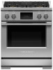
PROFESSIONAL RANGE RDV3-304, RIV3-304, RDV3-366, RIV3-365, RDV3-488, RDV3-485GD, RHV3-484, RDV3-486 models INSTALLATION GUIDE US CA - Fisher and Paykel RDV3-304-N | Installation Guide - Page 2
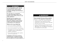
AND WARNINGS ! WARNING! If the information in this manual is not followed exactly, a fire or explosion the gas supplier's instructions. • If you cannot reach your gas supplier, call the fire department. Installation and service must be performed by a qualified installer, service agency or the gas - Fisher and Paykel RDV3-304-N | Installation Guide - Page 3
the range and be killed. • Install the anti-tip device to the structure by fastening the supplied bracket to the floor and wall following the instructions for installing the anti-tip device. • Engage the anti-tip device. • Re-engage the anti-tip device if the range is moved. WARNING! Extremely - Fisher and Paykel RDV3-304-N | Installation Guide - Page 4
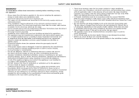
or maintenance can cause property damage, injury or death. Read the installation, operating and maintenance instructions thoroughly before using, installing or servicing this appliance. z A risk of the appliance tipping over exists if the appliance is not installed in accordance with installation - Fisher and Paykel RDV3-304-N | Installation Guide - Page 5
PARTS SUPPLIED FOR INSTALLATION Anti-tip bracket (1) #10 x 2" wood screws (4) 5/16" x 1 1/2" sleeve anchors (2) Lag bolts and washers (2) Foot cover sets (2) 5 - Fisher and Paykel RDV3-304-N | Installation Guide - Page 6
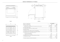
DIMENSIONS A Overall height of range (from floor to cook surface, excl. pan supports and vent trim) B Overall width of range C Overall depth of range (excl front of control panel F Height from top of cook surface to top of pan supports G Height from top of cook surface to top of z vent trim (as - Fisher and Paykel RDV3-304-N | Installation Guide - Page 7
DIMENSIONS A Overall height of range (from floor to cook surface, excl. pan supports and vent trim) B Overall width of range C Overall depth of range (excl front of control panel F Height from top of cook surface to top of pan supports G Height from top of cook surface to top of z vent trim (as - Fisher and Paykel RDV3-304-N | Installation Guide - Page 8
DIMENSIONS A Overall height of range (from floor to cook surface, excl. pan supports and vent trim) B Overall width of range C Overall depth of range (excl front of control panel F Height from top of cook surface to top of pan supports G Height from top of cook surface to top of z vent trim (as - Fisher and Paykel RDV3-304-N | Installation Guide - Page 9
CLEARANCE DIMENSIONS - ALL MODELS A E B C D C H G electrical and gas F ISO FRONT CLEARANCE DIMENSIONS A Minimum width of ventilation hood installed above range B Minimum vertical distance between countertop and cabinet extending above counter C Minimum clearance from left and right edge of - Fisher and Paykel RDV3-304-N | Installation Guide - Page 10
can be purchased separately. All ranges come fitted with an Integral Vent Trim only. For more information on Backguard installation, refer to the separate instructions provided with your backguard. Backguard Installation Instructions can also be downloaded from our website, www.fisherpaykel.com - Fisher and Paykel RDV3-304-N | Installation Guide - Page 11
VENTILATION REQUIREMENTS z Ventilation hoods and blowers are designed for use with single wall ducting, however some local building codes or inspectors may require double wall ducting and/or a damper. Consult local building codes and/or agencies before installing to ensure local requirements are - Fisher and Paykel RDV3-304-N | Installation Guide - Page 12
1. REMOVE TOE KICK UNPACKING THE RANGE 2. REMOVE DOORS 1 Remove both screws to detach the toe kick from the range. 1 Open the door completely and open the hinge locks fully on both sides. Refer to page 13 for more detail FRONT VIEW HINGE DETAIL Holding the door on both sides, 2 Lift toe - Fisher and Paykel RDV3-304-N | Installation Guide - Page 13
REMOVING AND REFITTING THE OVEN DOOR(S) IMPORTANT! z Take care, the oven door is heavy. z Do not lift the oven door by its handle. Doing so may damage the door. z Ensure the oven and the door are cool before you begin to remove the door. z Before removing the door, ensure there is a large enough - Fisher and Paykel RDV3-304-N | Installation Guide - Page 14
LOCATION OF ELECTRICAL AND GAS SUPPLY RDV3 & RHV3 MODELS RIV3 MODELS Final position of range against wall Final position of range against wall regulator* A A A A electricity and gas B electricity B C C SUPPLY AREA DIMENSIONS A Distance from either edge of range to supply area B Height - Fisher and Paykel RDV3-304-N | Installation Guide - Page 15
of which, observe National Electrical Code ANSI / NFPA No. 70. The rating label is located under the control panel Wiring diagrams are also in the service summary, attached to the inside of the toe kick panel A wiring diagram label is attached to the back of the range RDV3 models z A neutral - Fisher and Paykel RDV3-304-N | Installation Guide - Page 16
cord or cable assembly must be replaced by permanent connection (hard wired) using a 3-conductor cord or cable assembly. See manufacturer's instructions. PERMANENT CONNECTION Units may be hard wired to the power supply. The installer must provide approved flexible steel conduit, maximum 6ft (1.8m - Fisher and Paykel RDV3-304-N | Installation Guide - Page 17
. ough to allow for removal of cooktop for servicing. to Range Make sure the connector is located as instructions. See instructions following. GGAASS z The appliance must be isolated from the building's gas supply piping system by closing its individual manual - Fisher and Paykel RDV3-304-N | Installation Guide - Page 18
to final positioning. Refer to "Backguard considerations" for the backguard options. z Ensure all electrical and gas connections have been done as per instructions. z Ensure flooring and adjacent cabinetry are also level. To achieve a flush fit of the range to adjoining countertops, it will be - Fisher and Paykel RDV3-304-N | Installation Guide - Page 19
installed settings for the correct gas type. z If proper operation cannot be obtained, contact Customer Care or your nearest Fisher & Paykel Authorized Service Center. z The range and cooktop must not be used by the customer until proper operation has been achieved. LEAK TESTING GAS ON z Make - Fisher and Paykel RDV3-304-N | Installation Guide - Page 20
the range and be killed. • Install the anti-tip device to the structure by fastening the supplied bracket to the floor and wall following the instructions for installing the anti-tip device. • Engage the anti-tip device. • Re-engage the anti-tip device if the range is moved. All ranges must - Fisher and Paykel RDV3-304-N | Installation Guide - Page 21
natural gas or 10.0" W.C. for LP. F Manual gas shut-off valve installed in an accessible location. over-current protection is provided for service cord connection. F Adequate ground connection and door opens and closes properly. F Burner pan supports correctly positioned, level, and do not rock. F - Fisher and Paykel RDV3-304-N | Installation Guide - Page 22
may not be available in all markets and are subject to change at any time. The product specifications in this guide apply to the specific products and models described at the date of issue. Under our policy of continuous product improvement, these specifications may change at
-
 1
1 -
 2
2 -
 3
3 -
 4
4 -
 5
5 -
 6
6 -
 7
7 -
8
-
9
-
10
-
11
-
12
-
13
-
14
-
15
-
16
-
17
-
18
-
19
-
20
-
21
-
22
 |
 |

RDV3-304, RIV3-304,
RDV3-366, RIV3-365,
RDV3-488, RDV3-485GD,
RHV3-484, RDV3-486
models
PROFESSIONAL RANGE
INSTALLATION GUIDE
US CA