Frigidaire FEQ332ES Installation Instructions (All Languages) - Page 2
Exhaust System Requirements, Pre-installation Requirements, Electrical Requirements - installation instructions
 |
UPC - 012505374395
View all Frigidaire FEQ332ES manuals
Add to My Manuals
Save this manual to your list of manuals |
Page 2 highlights
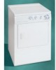
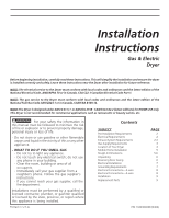
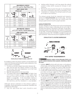
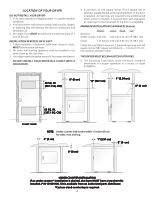
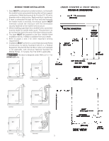
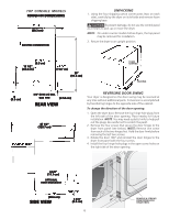
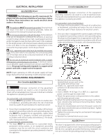
PRE-INSTALLATION REQUIREMENTS Tools and Materials Required for Installation: 1. Phillips head screwdriver. 2. Channel-lock adjustable pliers. 3. Carpenter's level. 4. Flat or straight blade screwdriver. 5. Duct tape. 6. Rigid or flexible metal 4 inch (10.2 cm) duct. 7. Vent hood. 8. Pipe thread sealer (Gas). 9. Plastic knife. ELECTRICAL REQUIREMENTS ELECTRIC Dryer CIRCUIT - Individual 30 amp. branch circuit fused with 30 amp. minimum time delay fuses or circuit breakers. POWER SUPPLY - 3 wire, 240 volt, single phase, 60 Hz, Alternating Current. (Canada - 240 volt, single phase, 60 Hz, Alternating Current.) POWER SUPPLY CORD KIT - The dryer MUST employ a 3conductor power supply cord NEMA 10-30 type SRDT rated at 240 volt AC minimum, 30 amp., with 3 open end spade lug connectors with upturned ends or closed loop connectors and marked for use with clothes dryers. If being installed in a manufactured (mobile) home, the dryer MUST employ a 4conductor power supply cord NEMA 14-30 type SRDT or ST (as required) rated at 240 volt AC minimum, 30 amp., with 4 open end spade lug connectors with upturned ends or closed loop connectors and marked for use with clothes dryers. See ELECTRICAL CONNECTIONS FOR A 4-WIRE SYSTEM. (Canada - 4-wire power supply cord is installed on dryer.) OUTLET RECEPTACLE - NEMA 10-30R receptacle to be located so the power supply cord is accessible when the dryer is in the installed position. (Canada - NEMA 14-30R receptacle.) POWER SUPPLY 3 WIRE GROUNDED NEUTRAL 120-240 VOLT 60 CYCLE MAIN FUSE BOX 30 AMP DELAYED ACTION FUSES OR CIRCUIT BREAKER NEUTRAL WIRE OUTLET RECEPTACLE (COPPER) SUBJECT TO LOCAL REGULATIONS NEMA 10-30R (COPPER) POWER SUPPLY CORD - The dryer is equipped with a 120 volt 3-wire power cord. NOTE: Do not under any circumstances remove grounding prong from plug. GROUNDING PRONG EXHAUST SYSTEM REQUIREMENTS Use only 4 inch (10.2 cm) diameter (minimum) rigid or flexible metal duct and approved vent hood which has a swing-out damper(s) that open when the dryer is in operation. When the dryer stops, the dampers automatically close to prevent drafts and the entrance of insects and rodents. To avoid restricting the outlet, maintain a minimum of 12 inches (30.5 cm) clearance between the vent hood and the ground or any other obstruction. The following are specific requirements for proper and safe operation of your dryer. Failure to follow these instructions can create excessive drying times and fire hazards. Do not use plastic flexible duct to exhaust the dryer. Excessive lint can build up inside exhaust system and create a fire hazard and restrict air flow. Restricted air flow will increase dryer times. If your present system is made up of plastic duct or metal foil duct, replace it with a rigid or flexible metal duct. Ensure the present duct is free of any lint prior to installing dryer duct. If the dryer is not exhausted outdoors, some fine lint will be expelled into the laundry area. An accumulation of lint in any area of the home can create a health and fire hazard. The dryer exhaust system MUST be exhausted to the outside of the dwelling! Do not allow combustible materials (for example: clothing, draperies/curtains, paper) to come in contact with exhaust system. The dryer MUST NOT be exhausted into a chimney, a wall, a ceiling, or any concealed space of a building which can accumulate lint, resulting in a fire hazard. Exceeding the length of duct pipe or number of elbows allowed in the "MAXIMUM LENGTH" charts can cause an accumulation of lint in the exhaust system. Plugging the system could create a fire hazard, as well as increase drying times. Do not screen the exhaust ends of the vent system, nor use any screws or rivets to assemble the exhaust system. Lint can become caught in the screen, on the screws or rivets, clogging the duct work and creating a fire hazard as well as increasing drying times. Use an approved vent hood to terminate the duct outdoors, and seal all joints with duct tape. All male duct pipe fittings MUST be installed downstream with the flow of air. GAS Dryer CIRCUIT - Individual 15 amp. branch circuit fused with a 15 amp. maximum time delay fuse or circuit breaker. Explosion hazard. Do not install the dryer where gasoline or other flammables are kept or stored. If the dryer is installed in a garage, it must be a minimum of 18 inches (45.7 cm) above the floor. Failure to do so can result in death, POWER SUPPLY - 3 wire, 120 volt single phase, 60 Hz, explosion, fire or burns. Alternating Current. 2
-
 1
1 -
 2
2 -
 3
3 -
 4
4 -
 5
5 -
 6
6 -
 7
7 -
 8
8 -
9
-
10
-
11
-
12
-
13
-
14
-
15
-
16
-
17
-
18
-
19
-
20
-
21
-
22
-
23
-
24
-
25
-
26
-
27
 |
 |