Garmin LiveScope LVS32-IF Installation Instructions
Garmin LiveScope LVS32-IF Manual
 |
View all Garmin LiveScope LVS32-IF manuals
Add to My Manuals
Save this manual to your list of manuals |
Garmin LiveScope LVS32-IF manual content summary:
- Garmin LiveScope LVS32-IF | Installation Instructions - Page 1
PANOPTIX™LIVESCOPE™ INSTALLATION INSTRUCTIONS Important Safety Information WARNING See the Important Safety and Product Information guide Garmin chartplotter software when you install this device. For instructions on updating the software, see your chartplotter owner's manual at support.garmin.com - Garmin LiveScope LVS32-IF | Installation Instructions - Page 2
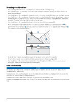
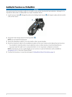
You should mount the transducer as close to the center line of the boat as possible. • When mounted farther from the due to repeated rotation of the motor. You should use black electrical tape to secure the cable above and . You should create a service loop at least 25 cm (10 in.) long in the - Garmin LiveScope LVS32-IF | Installation Instructions - Page 3
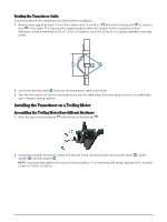
in both directions. Allow a minimum of 25 cm (10 in.) of cable to cover the 20 cm (8 in.) section between mounting points. 2 Use black electrical tape to secure the transducer cable to the shaft. 3 Test the full rotation of the trolling motor to ensure the cable clears the rotating joint and is not - Garmin LiveScope LVS32-IF | Installation Instructions - Page 4
when the trolling motor is deployed or stowed. NOTE: If necessary, for extra cable length you can connect an optional extension cable, available at buy.garmin.com or from your Garmin dealer. 5 Position the transducer to your desired angle (Trolling Motor Mount Orientation, page 5). 4 - Garmin LiveScope LVS32-IF | Installation Instructions - Page 5
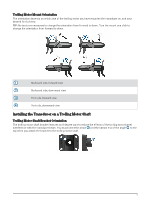
Trolling Motor Mount Orientation The orientation depends on which side of the trolling motor you have mounted the transducer on, and your desired field of view. TIP: No tools are necessary to change the orientation from forward to down. Turn the mount one click to change the orientation from forward - Garmin LiveScope LVS32-IF | Installation Instructions - Page 6
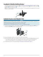
Assembling the Trolling Motor Shaft Mount Hardware With the trolling motor bracket oriented correctly (Trolling Motor Shaft Bracket Orientation, page 5), use the included hex wrench to attach the transducer to the trolling shaft bracket with the shoulder screw , flat washer , and rubber washer . - Garmin LiveScope LVS32-IF | Installation Instructions - Page 7
Go to buy.garmin.com or contact your Garmin dealer for information. Assembling the Transom-Mount Hardware 1 Attach the transducer mount bracket to the transducer washers . using the mounting screws and lock 2 Attach the transducer mount bracket to the transom mount bracket using the bolts , flat - Garmin LiveScope LVS32-IF | Installation Instructions - Page 8
cracking in the gel-coat layer when the screws are tightened. 1 Place the transducer mount so the top of the transducer is even with or up to 12.7 mm (1/2 in.) above the bottom edge of the transom. 2 Using the transom mount as a template, mark the location of the pilot holes. 3 Wrap a piece of tape - Garmin LiveScope LVS32-IF | Installation Instructions - Page 9
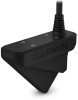
the GLS 10 Black Box Device NOTICE If you are mounting the device in fiberglass, when drilling the pilot holes, use a countersink bit to drill a clearance counterbore through only the top gel-coat layer. This will help to avoid cracking in the gel-coat layer when - Garmin LiveScope LVS32-IF | Installation Instructions - Page 10
the fuse. Removing the fuse may cause the device to malfunction and will void the warranty. Panoptix LiveScope GLS 10 power cable to POWER port Transducer cable to XDCR port Panoptix LiveScope LVS32 transducer 1 For chartplotter connections, refer to your chartplotter installation instructions. 10 - Garmin LiveScope LVS32-IF | Installation Instructions - Page 11
Power Cable Extensions If necessary, you can extend the power cable using the appropriate wire gauge for the length of the extension. Item Description Fuse Battery 9 ft. (2.7 m) no extension Item Description Splice • 10 AWG (5.26 mm²) extension - Garmin LiveScope LVS32-IF | Installation Instructions - Page 12
Transducer Settings and Operation For transducer settings and operation information, see your chartplotter owner's manual. Calibrating the Compass Before you can calibrate the compass, the transducer compass. NOTE: To use the compass, you must mount the transducer on the transom or the trolling motor - Garmin LiveScope LVS32-IF | Installation Instructions - Page 13
Specifications Panoptix LiveScope LVS32 Specifications Dimensions (L x H x W) Weight (transducer only) Frequencies Operating temperature Storage LiveScope™ and Panoptix™ are trademarks of Garmin Ltd. or its subsidiaries. These trademarks may not be used without the express permission of Garmin - Garmin LiveScope LVS32-IF | Installation Instructions - Page 14
© 2018 Garmin Ltd. or its subsidiaries support.garmin.com
-
 1
1 -
 2
2 -
 3
3 -
 4
4 -
 5
5 -
 6
6 -
 7
7 -
8
-
9
-
10
-
11
-
12
-
13
-
14
 |
 |
PANOPTIX
™
LIVESCOPE
™
INSTALLATION
INSTRUCTIONS
Important Safety Information
WARNING
See the
Important Safety and Product Information
guide in the chartplotter product box for product warnings
and other important information.
You are responsible for the safe and prudent operation of your vessel. Sonar is a tool that enhances your
awareness of the water beneath your boat. It does not relieve you of the responsibility of observing the water
around your boat as you navigate.
CAUTION
Failure to install and maintain this equipment in accordance with these instructions could result in damage or
injury.
To avoid possible personal injury, always wear safety goggles, ear protection, and a dust mask when drilling,
cutting, or sanding.
NOTICE
When drilling or cutting, always check what is on the opposite side of the surface to avoid damaging the vessel.
To obtain the best performance and to avoid damage to your boat, you must install the Garmin
®
device
according to these instructions.
Read all installation instructions before proceeding with the installation. If you experience difficulty during the
installation, go to
support.garmin.com
for more information.
Software
Update
You must update the Garmin chartplotter software when you install this device. For instructions on updating
the software, see your chartplotter owner's manual at
support.garmin.com
.
Tools Needed
•
Drill
•
4 mm (
5
/
32
in.) and 3.2 mm (
1
/
8
in.) drill bits
•
Masking tape
•
#2 Phillips screwdriver
•
Marine sealant
•
32 mm (1
1
/
4
in.) hole saw (optional)
•
Cable ties (optional)
GUID-8ABE5659-3192-4519-8A48-66421E004620 v5
March 2021