Gateway S-7510 Reference Guide - Page 104
remove it. Be careful not to break off the tabs located
 |
View all Gateway S-7510 manuals
Add to My Manuals
Save this manual to your list of manuals |
Page 104 highlights
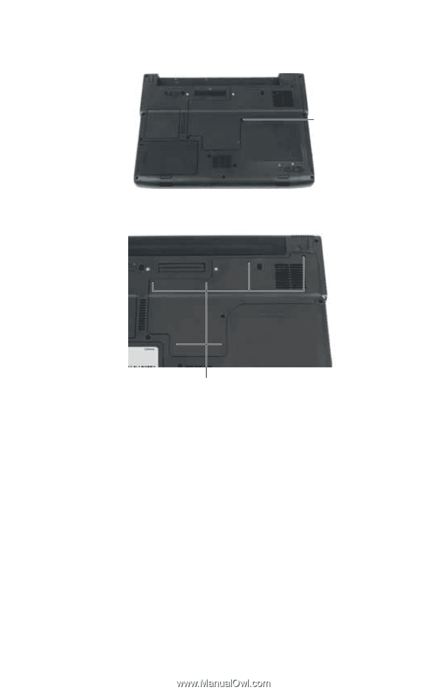
CHAPTER 8: Upgrading Your Notebook 7 Remove the keyboard screw. Screw 8 Loosen the six memory bay cover screws (these screws cannot be removed). Screws 9 Use the thumb notch to lift the memory bay cover, then remove it. Be careful not to break off the tabs located on the end of the cover opposite of the thumb notch. 96
-
 1
1 -
2
-
3
-
4
-
5
-
6
-
7
-
8
-
9
-
10
-
11
-
12
-
13
-
14
-
15
-
16
-
17
-
18
-
19
-
20
-
21
-
22
-
23
-
24
-
25
-
26
-
27
-
28
-
29
-
30
-
31
-
32
-
33
-
34
-
35
-
36
-
37
-
38
-
39
-
40
-
41
-
42
-
43
-
44
-
45
-
46
-
47
-
48
-
49
-
50
-
51
-
52
-
53
-
54
-
55
-
56
-
57
-
58
-
59
-
60
-
61
-
62
-
63
-
64
-
65
-
66
-
67
-
68
-
69
-
70
-
71
-
72
-
73
-
74
-
75
-
76
-
77
-
78
-
79
-
80
-
81
-
82
-
83
-
84
-
85
-
86
-
87
-
88
-
89
-
90
-
91
-
92
-
93
-
94
-
95
-
96
-
97
-
98
-
 99
99 -
 100
100 -
 101
101 -
 102
102 -
 103
103 -
 104
104 -
 105
105 -
 106
106 -
 107
107 -
 108
108 -
 109
109 -
110
-
111
-
112
-
113
-
114
-
115
-
116
-
117
-
118
-
119
-
120
-
121
-
122
-
123
-
124
-
125
-
126
-
127
-
128
-
129
-
130
-
131
-
132
-
133
-
134
-
135
-
136
-
137
-
138
-
139
-
140
-
141
-
142
-
143
-
144
-
145
-
146
-
147
-
148
-
149
-
150
-
151
-
152
-
153
-
154
-
155
-
156
-
157
-
158
-
159
-
160
-
161
-
162
-
163
-
164
 |
 |
CHAPTER
8
: Upgrading Your Notebook
96
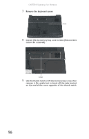
7
Remove the keyboard screw.
8
Loosen the six memory bay cover screws (these screws
cannot be removed).
9
Use the thumb notch to lift the memory bay cover, then
remove it. Be careful not to break off the tabs located
on the end of the cover opposite of the thumb notch.
Screw
Screws