GE DPGT750GCPL Owners Manual - Page 22
Installation Instructions, CONNECTING A GAS DRYER cont. - lp kit
 |
UPC - 084691079743
View all GE DPGT750GCPL manuals
Add to My Manuals
Save this manual to your list of manuals |
Page 22 highlights
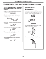
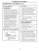
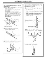
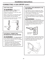
Installation Instructions CONNECTING A GAS DRYER (cont.) GAS REQUIREMENTS WARNING • Installation must conform to local codes and ordinances, or in their absence, the NATIONAL FUEL GAS CODE, ANSI Z223. • This gas dryer is equipped with a Valve and Burner Assembly for use only with natural gas. Using conversion kit WE25X10014, your local service organization can convert this dryer for use with propane (LP) gas. ALL CONVERSIONS MUST BE MADE BY PROPERLY TRAINED AND QUALIFIED PERSONNEL AND IN ACCORDANCE WITH LOCAL CODES AND ORDINANCE REQUIREMENTS. • The dryer must be disconnected from the gas supply piping system during any pressure testing of that system at a test pressure in excess of 0.5 PSI (3.4 KPa). • The dryer must be isolated from the gas supply piping system by closing the equipment shut-off valve during any pressure testing of the gas supply piping of test pressure equal to or less than 0.5 PSI (3.4KPa). DRYER GAS SUPPLY CONNECTION 31⁄4" (8.2 cm) 23⁄8" (6 cm) 3/8" NPT MALE THREAD GAS SUPPLY NOTE: Add to vertical dimension the distance between cabinet bottom to floor. GAS SUPPLY • A 1/8" National Pipe Taper thread plugged tapping, accessible for test gauge connection, must be installed immediately upstream of the gas supply connection to the dryer. Contact your local gas utility should you have questions on the installation of the plugged tapping. • Supply line is to be 1/2" rigid pipe and equipped with an accessible shut-off within 6 feet of, and in the same room with, the dryer. • Use pipe compound appropriate for natural or LP gas or use Teflon® tape. • Connect flexible metal connector to dryer and gas supply. IN THE COMMONWEALTH OF MASSACHUSETTS • This product must be installed by a licensed plumber or gas fitter. • When using ball-type gas shut-off valves, they shall be the T-handle type. • A flexible gas connector, when used, must not exceed 3 feet. ADJUSTING FOR ELEVATION • Gas clothes dryers input ratings are based on sea level operation and need not be adjusted for operation at or below 2000 ft. elevation. For operation at elevations above 2000 ft., input ratings should be reduced at a rate of 4 percent for each 1000 ft. above sea level. • Installation must conform to local codes and ordinances or, in their absence, the NATIONAL FUEL GAS CODE, ANSI Z223. 22
-
 1
1 -
2
-
3
-
4
-
5
-
6
-
7
-
8
-
9
-
10
-
11
-
12
-
13
-
14
-
15
-
16
-
 17
17 -
 18
18 -
 19
19 -
 20
20 -
 21
21 -
 22
22 -
 23
23 -
 24
24 -
 25
25 -
 26
26 -
 27
27 -
28
-
29
-
30
-
31
-
32
-
33
-
34
-
35
-
36
-
37
-
38
-
39
-
40
-
41
-
42
-
43
-
44
-
45
-
46
-
47
-
48
-
49
-
50
-
51
-
52
-
53
-
54
-
55
-
56
-
57
-
58
-
59
-
60
-
61
-
62
-
63
-
64
-
65
-
66
-
67
-
68
-
69
-
70
-
71
-
72
-
73
-
74
-
75
-
76
-
77
-
78
-
79
-
80
-
81
-
82
-
83
-
84
-
85
-
86
-
87
-
88
 |
 |
