GE DPGT750GCPL Owners Manual - Page 23
Installation Instructions
 |
UPC - 084691079743
View all GE DPGT750GCPL manuals
Add to My Manuals
Save this manual to your list of manuals |
Page 23 highlights
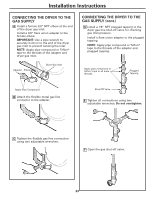
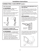
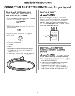
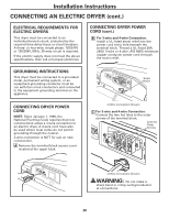
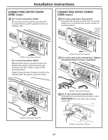
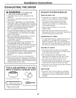
Installation Instructions CONNECTING THE DRYER TO THE GAS SUPPLY A Install a female 3/8" NPT elbow at the end of the dryer gas inlet. Install a 3/8" flare union adapter to the female elbow. IMPORTANT: Use a pipe wrench to securely hold on to the end of the dryer gas inlet to prevent twisting the inlet. NOTE: Apply pipe compound or Teflon® tape to the threads of the adapter and dryer gas inlet. Adapter Elbow Dryer Gas Inlet CONNECTING THE DRYER TO THE GAS SUPPLY (cont.) D Install a 1/8" NPT plugged tapping to the dryer gas line shut-off valve for checking gas inlet pressure. Install a flare union adapter to the plugged tapping. NOTE: Apply pipe compound or Teflon® tape to the threads of the adapter and plugged tapping. Apply pipe compound or Teflon® tape to all male threads. Plugged Tapping Apply Pipe Compound B Attach the flexible metal gas line connector to the adapter. Shut-Off Valve E Tighten all connections using two adjustable wrenches. Do not overtighten. C Tighten the flexible gas line connection using two adjustable wrenches. F Open the gas shut-off valve. 23
-
 1
1 -
2
-
3
-
4
-
5
-
6
-
7
-
8
-
9
-
10
-
11
-
12
-
13
-
14
-
15
-
16
-
17
-
 18
18 -
 19
19 -
 20
20 -
 21
21 -
 22
22 -
 23
23 -
 24
24 -
 25
25 -
 26
26 -
 27
27 -
 28
28 -
29
-
30
-
31
-
32
-
33
-
34
-
35
-
36
-
37
-
38
-
39
-
40
-
41
-
42
-
43
-
44
-
45
-
46
-
47
-
48
-
49
-
50
-
51
-
52
-
53
-
54
-
55
-
56
-
57
-
58
-
59
-
60
-
61
-
62
-
63
-
64
-
65
-
66
-
67
-
68
-
69
-
70
-
71
-
72
-
73
-
74
-
75
-
76
-
77
-
78
-
79
-
80
-
81
-
82
-
83
-
84
-
85
-
86
-
87
-
88
 |
 |
