GE DPGT750GCPL Owners Manual - Page 26
Installation Instructions, CONNECTING AN ELECTRIC DRYER cont.
 |
UPC - 084691079743
View all GE DPGT750GCPL manuals
Add to My Manuals
Save this manual to your list of manuals |
Page 26 highlights
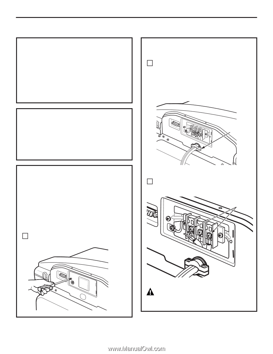
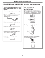
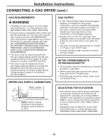
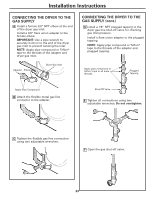
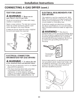
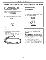
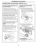
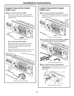
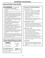
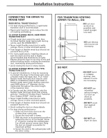
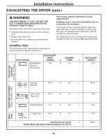
Installation Instructions CONNECTING AN ELECTRIC DRYER (cont.) ELECTRICAL REQUIREMENTS FOR ELECTRIC DRYERS This dryer must be connected to an individual branch circuit, protected by the required time-delay fuses or circuit breakers. A three- or four-wire, single phase, 120/240V or 120/208V, 60Hz, 30-amp circuit is required. If the electric supply does not meet the above specifications, then call a licensed electrician. CONNECTING DRYER POWER CORD (cont.) B For 3-wire and 4-wire Connection: Install a UL-listed strain relief into the power cord entry hole beneath the terminal block. Thread a UL-listed 30A, 240V, 3-wire or 4-wire, #10 AWG minimum copper conductor power cord through the strain relief. GROUNDING INSTRUCTIONS This dryer must be connected to a grounded metal, permanent wiring system, or an equipment-grounding conductor must be run with the circuit conductors and connected to the equipment grounding terminal on the appliance. Strain Relief CONNECTING DRYER POWER CORD NOTE: Since January 1, 1996, the National Electrical Code requires that new constructions utilize a 4-wire connection to an electric dryer. A 4-wire cord must also be used where local codes do not permit grounding through the neutral. 3-wire connection is NOT for use on new construction. A Remove the terminal block access cover located at the upper back. (3-Wire Connection Shown) C For 3-wire and 4-wire Connection: Connect the two hot lines to the outer screws of the terminal block. Connect Outer Screws (3-Wire Connection Shown) WARNING: Do not make a sharp bend or crimp wiring/conductor at connections. 26
-
 1
1 -
2
-
3
-
4
-
5
-
6
-
7
-
8
-
9
-
10
-
11
-
12
-
13
-
14
-
15
-
16
-
17
-
18
-
19
-
20
-
 21
21 -
 22
22 -
 23
23 -
 24
24 -
 25
25 -
 26
26 -
 27
27 -
 28
28 -
 29
29 -
 30
30 -
 31
31 -
32
-
33
-
34
-
35
-
36
-
37
-
38
-
39
-
40
-
41
-
42
-
43
-
44
-
45
-
46
-
47
-
48
-
49
-
50
-
51
-
52
-
53
-
54
-
55
-
56
-
57
-
58
-
59
-
60
-
61
-
62
-
63
-
64
-
65
-
66
-
67
-
68
-
69
-
70
-
71
-
72
-
73
-
74
-
75
-
76
-
77
-
78
-
79
-
80
-
81
-
82
-
83
-
84
-
85
-
86
-
87
-
88
 |
 |