GE GTUP240EMWW Installation Instructions
GE GTUP240EMWW Manual
 |
UPC - 084691228998
View all GE GTUP240EMWW manuals
Add to My Manuals
Save this manual to your list of manuals |
GE GTUP240EMWW manual content summary:
- GE GTUP240EMWW | Installation Instructions - Page 1
to water and or weather. • Save these instructions. (Installers: Be sure to leave these instructions with the customer). NOTE: Installation and service of this appliance requires basic mechanical and electrical skills. It is your responsibility to contact a qualified installer to make the electrical - GE GTUP240EMWW | Installation Instructions - Page 2
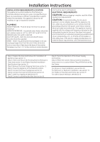
Installation Instructions INSTALLATION REQUIREMENTS LOCATION This appliance must be installed on firm flooring to minimize vibration during spin cycle. Concrete flooring is best, but wood base is sufficient, provided floor support meets FHA standards. This appliance should not be installed on rugs - GE GTUP240EMWW | Installation Instructions - Page 3
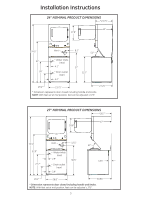
Installation Instructions 24" NOMINAL PRODUCT DIMENSIONS *23.75" 43" 17.9" 74.5" Vent 8.2" 51° 51" 26" Water inlets (rear) 4.1" Drain outlet (rear) 4.2" 37" 32.7" 19.1" 23.75" 27.25" * Dimension represents door closed including handle and knobs. NOTE: With feet set at mid position, feet - GE GTUP240EMWW | Installation Instructions - Page 4
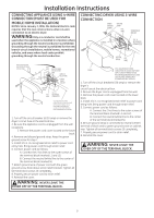
containing the Washer hoses and parts parts from tub. Put Washer hoses styrofoam block back in tub and parts opening to hold tub in place during the rest of installation. Move washer close to final position. Make sure there is at least a 24" clearance on right side of washer to remove shipping - GE GTUP240EMWW | Installation Instructions - Page 5
Installation Instructions CONNECTING APPLIANCE USING 4-WIRE CONNECTION (MUST BE USED FOR MOBILE HOME INSTALLATION) NOTES: SInce January 1,1996, the National Electric code requires that the new constructions utilize a 4-wire connection to an electric dryer. WARNING:Only a 4-conductor cord shall be - GE GTUP240EMWW | Installation Instructions - Page 6
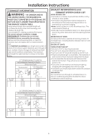
Installation Instructions 3 EXHAUST INFORMATION WARNING - IN CANADA AND IN THE UNITED STATES, THE REQUIRED energy cost. • Reduce the dryer life. • Accumulate lint, creating a potential fire hazard. The correct exhaust installation is YOUR RESPONSIBILITY. Problems due to incorrect installation - GE GTUP240EMWW | Installation Instructions - Page 7
or UL-listed flexible metal (semi-rigid or foil-type) duct to connect the dryer to the home exhaust duct. It must be installed in accordance with the instructions found in "Connecting The Dryer To House Vent" on page 8 of this manual. • Do not terminate exhaust in a chimney, a wall, a ceiling, gas - GE GTUP240EMWW | Installation Instructions - Page 8
Installation Instructions CONNECTING THE DRYER TO HOUSE VENT RIGID METAL TRANSITION DUCT • For best drying performance, Canada and the United States, only the flexible metal(foiltype) ducts that comply with the "Outline for Clothes Dryer Transition Duct Subject 2158A" shall be used. • Never install - GE GTUP240EMWW | Installation Instructions - Page 9
Installation Instructions 6 DRYER EXHAUST TO RIGHT, LEFT OR BOTTOM CABINET WARNING - BEFORE PERFORMING THIS EXHAUST INSTALLATION, BE SURE TO DISCONNECT THE APPLIANCE FROM ITS ELECTRICAL SUPPLY. PROTECT YOUR HANDS AND ARMS FROM SHARP EDGES WHEN WORKING INSIDE THE CABINET. BE SURE TO WEAR GLOVES For - GE GTUP240EMWW | Installation Instructions - Page 10
rear of washer. Hand tighten, plus an additional 1/8 turn with pliers. Move appliance as close to final location as possible, leaving room for you to make water, drain, electrical and vent connections to your home. NOTE: If longer drain hose is required, order drain hose extension kit, GE part number - GE GTUP240EMWW | Installation Instructions - Page 11
of the exhaust vent . • See section 2 for electrical connection information. DOOR VENTILATION OPENING (27" MODELS) A minimum of 120 square inches of opening, equally divided at top and bottom, is required. Air openings are required to be unobstructed when a door is installed. A louvered door with - GE GTUP240EMWW | Installation Instructions - Page 12
ALL WIRES PRIOR TO DISCONNECTION WHEN SERVICING CONTROLS. WIRING ERRORS CAN CAUSE IMPROPER AND DANGEROUS OPERATION AFTER SERVICING/INSTALLATION. For replacement parts and other information, refer to Owner's Manual for servicing phone numbers. TO REGISTER YOUR DRYER CALL TOLL-FREE 1-888-269-1192 - GE GTUP240EMWW | Installation Instructions - Page 13
TODOS LOS CABLES ANTES DE LA DESCONEXIÓN CUANDO SE REALICEN CONTROLES DEL SERVICIO TÉCNICO. CUALQUIER ERROR DE CABLEADO PUEDE OCASIONAR otras informaciones, consulte los números telefónicos del servicio técnico en el Manual del Propietario. PARA REGISTRAR SU SECADORA LLAME AL NÚMERO GRATUITO 1-888- - GE GTUP240EMWW | Installation Instructions - Page 14
CASAS PREFABRICADAS, TÍTULO 24, PARTE 32-80 (MANUFACTURED HOME CONSTRUCTION & SAFETY STANDARD, TITLE 24, PART 32-80) o, en la parte superior e inferior. Se requiere que las aberturas de aire no estén obstruidas cuando se instale una puerta. (NATIONAL ELECTRICAL CODE), ANSI/ NFPA NO. 70. 11 - GE GTUP240EMWW | Installation Instructions - Page 15
parte superior trasera de la lavadora. Ajuste manualmente, además de dar un giro adicional de 1/8 con una pinza. Si no se encuentra instalada, instale la un kit de extensión de manguera de drenaje; el número de pieza de GE es WH49X301. Conecte la manguera de drenaje adicional (incluida con el kit) - GE GTUP240EMWW | Installation Instructions - Page 16
Instrucciones de Instalación 6 SALIDA DE LA SECADORA HACIA EL GABINETE DERECHO, IZQUIERDO O INFERIOR ADVERTENCIA- ANTES DE REALIZAR LA INSTALACIÓN DE ESTE ESCAPE, ASEGÚRESE DE DESCONECTAR EL ELECTRODOMÉSTICO DE SU SUMINISTRO ELÉCTRICO. PROTEJA SUS MANOS Y BRAZOS DE EXTREMOS CORTANTES AL TRABAJAR - GE GTUP240EMWW | Installation Instructions - Page 17
) que cumplan con el "Resumen del Tema 2158A de Conductos de Transición para Secadoras de Ropa" (Outline for Clothes Dryer Transition Duct Subject 2158A). • Nunca instale un conducto de metal flexible en paredes, cielos rasos, pisos u otros espacios adjuntos. • La longitud total del conducto de - GE GTUP240EMWW | Installation Instructions - Page 18
la Ventilación del Hogar" en la página 8 de este manual. •No termine la salida del escape en una chimenea, pared, creando un posible riesgo de incendio. •Nunca instale una rejilla en o sobre el conducto de escape un nivel sobre la parte trasera de la tapa de la lavadora y controle la misma de un - GE GTUP240EMWW | Installation Instructions - Page 19
Pies 33 Pies 24 Pies 4" Metal Rígido 36 Pies 26 Pies 16 Pies INFORMACIÓN SOBRE EL ESCAPE LISTA DE CONTROL DEL SISTEMA DE mantenimiento para evitar obstrucciones. •Nunca instale una rejilla en o sobre el superpuesta con cinta para conducto. • Las partes horizontales deberán tener una caída de - GE GTUP240EMWW | Installation Instructions - Page 20
el cable de la secadora esté desenchufado del receptáculo de la pared. 3. Retire la tapa del cable de corriente ubicada en la parte inferior trasera. 4. Instale el amortiguador con refuerzo de ¾ pulgadas listado por UL del agujero de entrada del cable de corriente. Pase el cable de corriente por - GE GTUP240EMWW | Installation Instructions - Page 21
ambos lados y 1 pulgada en la parte trasera. Se deberá considerar que se debe 12" ABERTURA INTERNA DEL CONDUCTO CONTROLE QUE EL REGULADOR DE LA con el CÓDIGO NACIONAL DE ELECTRICIDAD (NATIONAL ELECTRICAL CODE), ANSI/NFPA NO. 70. Una de que haya por lo menos 24" de espacio sobre el lado derecho - GE GTUP240EMWW | Installation Instructions - Page 22
Instrucciones de Instalación DIMENSIONES NOMINALES DEL PRODUCTO DE 24" *23.75" 43" 17.9" 74.5" Ventilación 8.2" 51° 51" 26" Entradas de agua (trasera) 4.1" Salida de drenaje (trasera) 4.2" 37" 32.7" 19.1" 23.75" 27.25" * La - GE GTUP240EMWW | Installation Instructions - Page 23
la frecuencia indicados en la placa de especificaciones (ubicada en la parte superior del panel frontal de la lavadora), y estar conectado a un la sección 8). Paso 9 Controle el Funcionamiento del Cable de Corriente y la Ventilación. Paso 10 Coloque el Manual del Propietario y las Instrucciones de - GE GTUP240EMWW | Installation Instructions - Page 24
de cerca.• Instale la secadora donde la temperatura supere los 50°F, para un funcionamiento satisfactorio del sistema de control de la secadora la Ventilación de la Casa" en la página 8 de este manual. Se sabe que los materiales flexibles para ventilación colapsan, se rompen con 29/10 GE
-
 1
1 -
 2
2 -
 3
3 -
 4
4 -
 5
5 -
 6
6 -
 7
7 -
8
-
9
-
10
-
11
-
12
-
13
-
14
-
15
-
16
-
17
-
18
-
19
-
20
-
21
-
22
-
23
-
24
 |
 |

189D7219P002
31-16652
10/29/10 GE
WARNING
RISK OF FIRE
• To reduce the risk of severe injury or death, follow all installation
instructions.
• Appliance installation must be performed by a qualified installer.
• Install the appliance according to these instructions and in accordance
with local codes.
• This appliance must be exhausted to the outdoors.
• Use only 4” rigid metal ducting for exhausting the clothes dryer to the
outdoors.
•
DO NOT
install a clothes dryer with flexible plastic ducting materials.
If flexible metal (semi-rigid or foil-type) duct is installed, it must be
UL listed and installed in accordance with the instructions found in
“Connecting The Dryer To House Vent” on page 8 of this manual.
Flexible venting materials are known to collapse, be easily crushed,
and trap lint. These conditions will obstruct dryer airflow and increase
the risk of fire.
• Do not install or store this appliance in any location where it could be
exposed to water and or weather.
• Save these instructions. (Installers: Be sure to leave these instructions
with the customer).
NOTE:
Installation and service of this appliance requires basic
mechanical and electrical skills. It is your responsibility to
contact a qualified installer to make the electrical connections.
Installation
Instructions
Unitized Electric
Washer/Dryer
Questions on Installation? Call: 1-800-GECARES (US)
or Visit our Web site at:
www.GEAppliances.com (US)
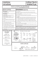
BEFORE YOU BEGIN
Read these instructions completely and carefully.
•
IMPORTANT-
Save these instructions for
local inspector’s use.
•
IMPORTANT-
Observe all
governing codes
and ordinances.
•
Note to Installer -
Be sure to leave these
instructions with the customer.
•
Note to Customer -
Keep these instructions
with your Use and Care Book for future
reference.
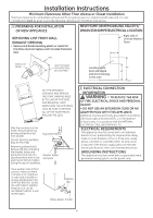
• Before the appliance is removed from service
or discarded, remove the washer and dryer
doors.
• Inspect the dryer exhaust outlet and straighten
the outlet walls if they are bent.
• Service information and the wiring diagram
are located at the access panel.
• Do not allow children on or in the appliance.
Close supervision of children is necessary
when the appliance is used near children.
• Install the appliance where the temperature is
above 50°F for satisfactory operation of the
control system.
MATERIALS YOU WILL NEED
GLOVES
SAFETY
GLASSES
APPLIANCE POWER
CORD KIT
(NOT PROVIDED)
4" DUCT
CLAMPS (2)
OR
4" SPRING
CLAMPS (2)
EXHAUST
HOOD
3/4" STRAIN
RELIEF
UL RECOGNIZED
4" DIA. METAL
ELBOW
DUCT TAPE
UL RATED
120/240V,30A
WITH 3 OR 4 PRONGS.
IDENTIFY THE PLUG
TYPE AS PER THE
HOUSE RECEPTACLE
BEFORE PURCHASING
LINE CORD.
4" DIA. FLEXIBLE METAL (SEMI-RIGID)
UL LISTED TRANSITION DUCT
(IF NEEDED)
KIT WX08X10077 (INCLUDES 2 ELBOWS)
4" DIA. METAL DUCT
(RECOMMENDED)
4" DIA. FLEXIBLE METAL (FOIL TYPE)
UL LISTED TRANSITION DUCT
(IF NEEDED.)
4" COVER PLATE (IF NEEDED)
(KIT WE1M454)
TOOLS YOU WILL NEED
Slip Pliers
Phillips Screwdriver
Flat-blade Screwdriver
1/4” Nutdriver
Level
PARTS SUPPLIED
2 Rubber Washers
2 Stainer Screens/
Ruuber Washers
(washers may be in water hoses)
2 Washer Hoses
1 Cable Tie