GE GTUP240EMWW Installation Instructions - Page 4
Warning - parts
 |
UPC - 084691228998
View all GE GTUP240EMWW manuals
Add to My Manuals
Save this manual to your list of manuals |
Page 4 highlights
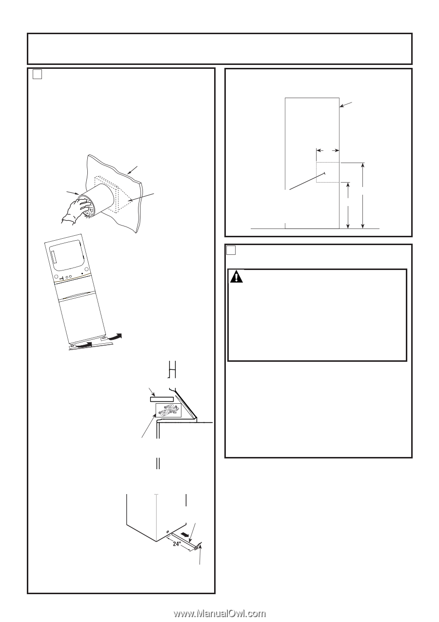
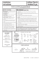
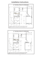
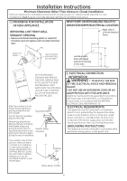
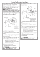
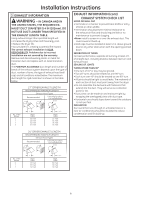
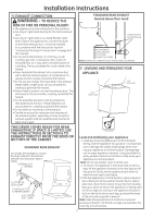
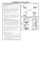
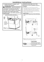
Installation Instructions Minimum Clearance Other Than Alcove or Closet Installation Minimum clearance to combustible surfaces and for air opening are: 0 in. clearance both sides and 1 in. rear. Consideration must be given to provide adequate clearance for installation and service. 1 PREPARING FOR INSTALLATION OF NEW APPLIANCE NEW HOME OR REMODELING FAUCETS/ DRAIN STANDPIPE/ELECTRICAL LOCATION REMOVING LINT FROM WALL EXHAUST OPENING • Remove and discard existing plastic or metal foil transition duct and replace with UL listed transition duct . Right side of Unitized Washer/ Dryer. 12" WALL INTERNAL DUCT OPENING CHECK THAT EXHAUST HOOD DAMPER OPENS AND CLOSES FREELY. Locate spigots, drain standpipe and electrical plug in this area 42" 33" FLOOR TILT THE APPLIANCE SIDEWAYS AND REMOVE THE FOAM SHIPPING PADS BY PULLING AT THE SIDES AND BREAKING THEM AWAY FROM THE APPLIANCE LEGS. BE SURE TO REMOVE ALL OF THE FOAM PIECES AROUND THE LEGS. After the machine is in the home, remove remaining packing material/carton from washer. Styrofoam Block DO NOT REMOVE SHIPPING ROD AT THIS TIME. Remove styrofoam block. Remove the bag containing the Washer hoses and parts parts from tub. Put Washer hoses styrofoam block back in tub and parts opening to hold tub in place during the rest of installation. Move washer close to final position. Make sure there is at least a 24" clearance on right side of washer to remove shipping bar. PULL SHIPPING BAR OUT USING YELLOW PLASTIC HANDLE. Keep bar so it can be reinstalled if washer is ever moved again. Shipping Bar Yellow plastic handle 2 ELECTRICAL CONNECTION INFORMATION WARNING - TO REDUCE THE RISK OF FIRE, ELECTRICAL SHOCK AND PERSONAL INJURY: • DO NOT USE AN EXTENSION CORD OR AN ADAPTER PLUG WITH THIS APPLIANCE. Appliance must be electrically grounded in accordance with local codes and ordinances, or in the absence of local codes, in accordance with the NATIONAL ELECTRICAL CODE, ANSI/NFPA NO. 70. ELECTRICAL REQUIREMENTS This appliance must be connected to an individual branch circuit, protected by the required time-delay fuses or circuit breakers. A four or three-wire, single phase, 120/240V or 120/208V, 60Hz, 30 amp circuit is required. If the electric supply does not meet the above specifications, then call a licensed electrician. GROUNDING INSTRUCTIONS This appliance must be connected to a grounded metal, permanent wiring system, via the power cord. 4
-
 1
1 -
 2
2 -
 3
3 -
 4
4 -
 5
5 -
 6
6 -
 7
7 -
 8
8 -
 9
9 -
 10
10 -
11
-
12
-
13
-
14
-
15
-
16
-
17
-
18
-
19
-
20
-
21
-
22
-
23
-
24
 |
 |