GE GTUP240EMWW Installation Instructions - Page 5
Connecting Appliance Using 4-wire, Connection Must Be Used For, Mobile Home Installation, Connecting - power requirements
 |
UPC - 084691228998
View all GE GTUP240EMWW manuals
Add to My Manuals
Save this manual to your list of manuals |
Page 5 highlights
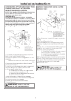
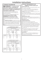
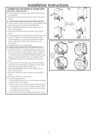
Installation Instructions CONNECTING APPLIANCE USING 4-WIRE CONNECTION (MUST BE USED FOR MOBILE HOME INSTALLATION) NOTES: SInce January 1,1996, the National Electric code requires that the new constructions utilize a 4-wire connection to an electric dryer. WARNING:Only a 4-conductor cord shall be used when the appliance is installed in a location where grounding through the neutral conductor is prohibited. Grounding through the neutral is prohibited for the new branch-circuit installations, mobile homes, recreational vehicles, and areas where local codes prohibit grounding through the neutral conduction. CONNECTING DRYER USING 3-WIRE CONNECTION GREEN GROUND SCREW GROUND STRAP HOT WIRE STRAIN RELIEF BRACKET L1 SCREWS (3) L2 3/4", UL RECOGNIZED STRAIN RELIEF NEUTRAL (White) HOT WIRE REMOVE GROUND STRAP AND DISCARD. KEEP GREEN GROUND SCREW SCREWS (3) COVER HOT WIRE L1 N L2 RELOCATE GREEN GROUND SCREW HERE GREEN OR YELLOW WIRE STRAIN RELIEF BRACKET NEUTRAL (White) HOT WIRE 3/4", UL RECOGNIZED STRAIN RELIEF 4 #10 AWG MINIMUM COPPER CONDUCTORS OR 120/240V 30A POWER SUPPLY CORD KIT MARKED FOR USE WITH DRYERS & PROVIDED WITH CLOSED LOOP OR SPADE TERMINALS WITH UPTURNED ENDS (NOT SUPPLIED). 1. Turn off the circuit breaker (s) (30 amp) or remove the dryer's circuit fuse at the electrical box. 2. Be sure the appliance cord is unplugged from the wall receptacle. 3. Remove the power cord cover located at the lower back. 4. Remove and discard ground strap. Keep the green ground screw for step 7. 5. Install 3/4 in. UL recognized strain relief to power cord entry hole. Bring power cord through strain relief. 6. Connect power cord as follows: A. Connect the 2 hot lines to the outer screws of the terminal block (marked L1 and L2). B. Connect the neutral (white) line to the center of the terminal block (marked N). 7. Attach ground wire of power cord with the green ground screw (hole above strain relief bracket). Tighten all terminal block screws (3) completely. 8. Properly secure power cord to strain relief. 9. Reinstall the cover. WARNING: NEVER LEAVE THE COVER OFF OF THE TERMINAL BLOCK. COVER 3 #10 AWG MINIMUM COPPER CONDUCTORS OR 120/240V 30A POWER SUPPLY CORD KIT MARKED FOR USE WITH DRYERS & PROVIDED WITH CLOSED LOOP OR SPADE TERMINALS WITH UPTURNED ENDS (NOT SUPPLIED). 1. Turn off the circuit breaker(s) (30 amp) or remove the dryer's circuit fuse at the electrical box. 2. Be sure the dryer cord is unplugged from the wall. 3. Remove the power cord cover located at the lower back. 4. Install 3/4 in. UL recognized strain relief to power cord entry hole. Bring power cord through strain relief. 5. Connect power cord as follows: A. Connect the 2 hot lines to the outer screws of the terminal block (marked L1 and L2). B. Connect the neutral (white) line to the center of the terminal block (marked N). 6. Be sure ground strap is connected to neutral (center) terminal of block and to green ground screw on cabinet rear. Tighten all terminal block screws (3) completely. 7. Properly secure power cord to strain relief. 8. Reinstall the cover. WARNING: NEVER LEAVE THE COVER OFF OF THE TERMINAL BLOCK. 5
-
 1
1 -
 2
2 -
 3
3 -
 4
4 -
 5
5 -
 6
6 -
 7
7 -
 8
8 -
 9
9 -
 10
10 -
 11
11 -
12
-
13
-
14
-
15
-
16
-
17
-
18
-
19
-
20
-
21
-
22
-
23
-
24
 |
 |
