GE GTUP240EMWW Installation Instructions - Page 7
Exhausting. If Space Is Limited, Use - instruction manual
 |
UPC - 084691228998
View all GE GTUP240EMWW manuals
Add to My Manuals
Save this manual to your list of manuals |
Page 7 highlights
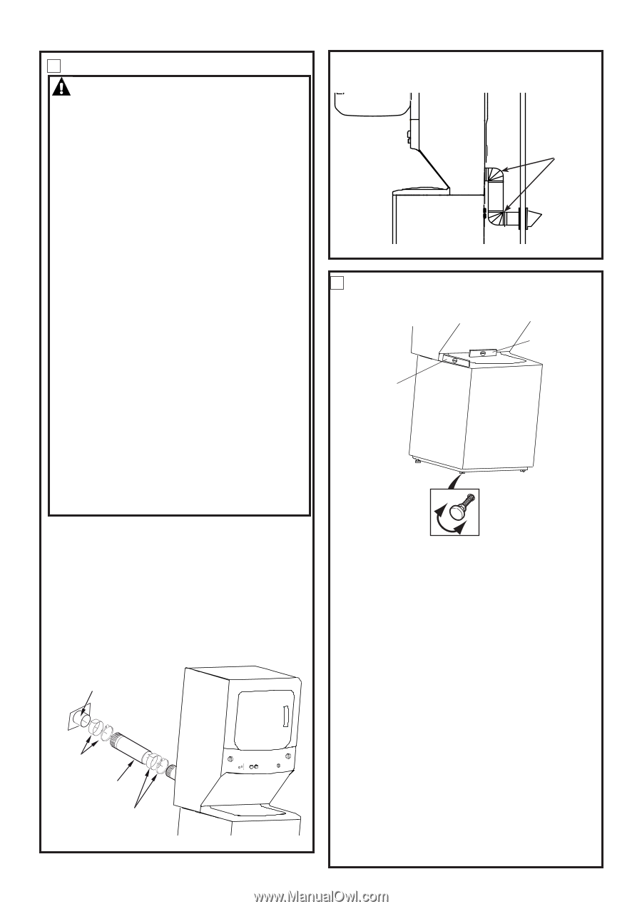
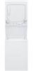
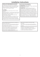
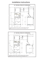
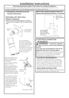
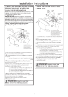
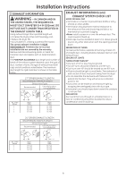
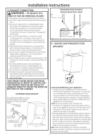
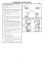
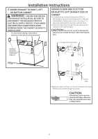
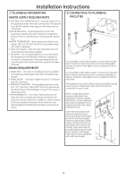
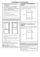
Installation Instructions 4 EXHAUST CONNECTION WARNING - TO REDUCE THE RISK OF FIRE OR PERSONAL INJURY: • This appliance must be exhausted to the outdoors. • Use only 4" rigid metal ducting for the home exhaust duct . • Use only 4" rigid metal or UL-listed flexible metal (semi-rigid or foil-type) duct to connect the dryer to the home exhaust duct. It must be installed in accordance with the instructions found in "Connecting The Dryer To House Vent" on page 8 of this manual. • Do not terminate exhaust in a chimney, a wall, a ceiling, gas vent, crawl space, attic, under an enclosed floor, or in any other concealed space of a building. The accumulated lint could create a fire hazard. • Never terminate the exhaust into a common duct with a kitchen exhaust system. A combination of = grease and lint creates a potential fire hazard. • Do not use duct longer than specified in the exhaust length table. Longer ducts can accumulate lint, creating a potential fire hazard. • Never install a screen in or over the exhaust duct. This will cause lint to accumulate, creating a potential fire hazard. • Do not assemble ductwork with any fasteners that extend into the duct. These fasteners can accumulate lint, creating a potential fire hazard. • Do not obstruct incoming or exhausted air. • Provide an access for inspection and cleaning of the exhaust system, especially at turns and joints. Exhaust system shall be inspected and cleaned at least once a year. STANDARD REAR EXHAUST (Vented above floor level) ELBOW HIGHLY RECOMMENDED RECOMMENDED CONFIGURATION TO MINIMIZE EXHAUST BLOCKAGE NOTE: ELBOWS WILL PREVENT DUCT KINKING AND COLLAPSING 5 LEVELING AND STABILIZING YOUR APPLIANCE LEVEL SIDE-TO-SIDE. LEVEL FRONT-TO-BACK. THIS DRYER COMES READY FOR REAR EXHAUSTING. IF SPACE IS LIMITED, USE THE INSTRUCTIONS IN SECTION 6 TO EXHAUST DIRECTLY FROM THE SIDES OR BOTTOM OF THE CABINET. STANDARD REAR EXHAUST For straight line installation, connect the dryer exhaust to the external exhaust hood using duct tape or clamp. EXTERNAL DUCT OPENING DUCT TAPE OR DUCT CLAMP 4" METAL DUCT CUT TO PROPER LENGTH DUCT TAPE OR DUCT CLAMP 2 LEVELING LEGS Level and stabilizing your appliance 1. Carefully move the appliance to its final location. Gently rock the appliance into position. It is important not to damage the rubber leveling legs when moving your appliance to its final location. Damage legs can increase appliance vibration. It may be helpful to spray window cleaner on the floor to help move your appliance to its final position. Note: do not use washer cover to lift the unit. 2. To ensure the appliance is level and solid on all four legs, tilt the appliance forward so the rear legs are off the ground. Gently set the appliance back down to allow the rear legs to self adjust. 3. With the appliance in its final position, place a level on top of back part of the washer lid and check it side to side, then check front to back. Screw the front leveling legs up or down to ensure the appliance is resting solid on all four legs (no rocking or the appliance should exist), turn the lock nuts on each leg up toward the base of the unit and snug with a wrench. Note: Keep the leg extension at minimum to prevent excessive vibration. The farther out legs are extended, the more the unit will vibrate. 7
-
 1
1 -
 2
2 -
 3
3 -
 4
4 -
 5
5 -
 6
6 -
 7
7 -
 8
8 -
 9
9 -
 10
10 -
 11
11 -
 12
12 -
13
-
14
-
15
-
16
-
17
-
18
-
19
-
20
-
21
-
22
-
23
-
24
 |
 |