Gigabyte GA-8IPE1000 Pro-G User Manual
Gigabyte GA-8IPE1000 Pro-G Manual
 |
View all Gigabyte GA-8IPE1000 Pro-G manuals
Add to My Manuals
Save this manual to your list of manuals |
Gigabyte GA-8IPE1000 Pro-G manual content summary:
- Gigabyte GA-8IPE1000 Pro-G | User Manual - Page 1
4X(1.5V) mode AGP slot, but they support 2X (3.3V) only. The GA-8IPE1000 Series (or any AGP 4X/8X only) motherboards might not function properly, If you install this card in it. Note : Although Gigabyte's AG32S(G) graphics card is based on ATi Rage 128 Pro chip, the design of AG32S(G) is compliance - Gigabyte GA-8IPE1000 Pro-G | User Manual - Page 2
may appear in this document nor does the author make a commitment to update the information contained herein. M Third-party brands and names are the owners. M Please do not remove any labels on motherboard, this may void the warranty of this motherboard. M Due to rapid change in technology, some - Gigabyte GA-8IPE1000 Pro-G | User Manual - Page 3
, 20537 Hamburg, Germany declare that the product ( description of the apparatus, system, installation to which it refers) Mother Board GA-8IPE1000 Pro-G/GA-8IPE1000-G/GA-8IPE1000 is in conformity with (reference to the specification under which conformity is declared) in accordance with 89/336 EEC - Gigabyte GA-8IPE1000 Pro-G | User Manual - Page 4
, CA 91748 Phone/Fax No: (818) 854-9338/ (818) 854-9339 hereby declares that the product Product Name: Motherboard Model Number: GA-8IPE1000 Pro-G/GA-8IPE1000-G/ GA-8IPE1000 Conforms to the following specifications: FCC Part 15, Subpart B, Section 15.107(a) and Section 15.109 (a),Class B Digital - Gigabyte GA-8IPE1000 Pro-G | User Manual - Page 5
GA-8IPE1000 Series P4 Titan Series Motherboard USER'S MANUAL Pentium®4 Processor Motherboard Rev. 3001 12ME-8IPE1KG-3001 - Gigabyte GA-8IPE1000 Pro-G | User Manual - Page 6
18 Step 4-2: Connectors & Jumper Setting Introduction 20 Chapter 3 BIOS Setup 35 The Main Menu (For example: BIOS Ver.: 8IPE1000 Pro-G.E1 36 Standard CMOS Features 38 Advanced BIOS Features 41 Integrated Peripherals 43 Power Management Setup 48 GA-8IPE1000 Series Motherboard - 2 - - Gigabyte GA-8IPE1000 Pro-G | User Manual - Page 7
TuneTM 4 Introduction 64 Face-WizardTM Utilities Installation 65 Flash BIOS Method Introduction 66 2-/4-/6-/8-Channel Audio Function Introduction 87 Jack-Sensing(UAJ) Introduction 93 Xpress Recovery Introduction 95 Chapter 5 Appendix 99 (*) For GA-8IPE1000 Pro-G only. - 3 - Table of Content - Gigabyte GA-8IPE1000 Pro-G | User Manual - Page 8
the motherboard PCB surface, because the circuit wire may be near by the hole. Be careful, don't let the screw contactany printed circuitwrite or parts on the PCB thatare near the fixing hole, otherwise it may damage the board or cause board malfunctioning. GA-8IPE1000 Series Motherboard - 4 - - Gigabyte GA-8IPE1000 Pro-G | User Manual - Page 9
Form Factor Motherboard CPU Chip set Memory I/O Control Slots On-Board IDE Serial ATA - 30.5cm x 23.0cm ATX size form factor, 4 layers PCB. - GA-8IPE1000 Series Motherboard: GA-8IPE1000 Pro-G/GA-8IPE1000-G/GA-8IPE1000 - Socket 478 for Intel® Micro FC-PGA2 Pentium® 4 processor - Support Intel - Gigabyte GA-8IPE1000 Pro-G | User Manual - Page 10
- Ti TSB43AB23 - PS/2 Keyboard interface and PS/2 Mouse interface - Licensed AWARD BIOS - Supports Dual BIOS (*)/Q-Flash - Supports Multi Language (*) - Supports Face Wizard (*) to be continued...... (*) For GA-8IPE1000 Pro-G only. (u) For GA-8IPE1000-G only. GA-8IPE1000 Series Motherboard - 6 - - Gigabyte GA-8IPE1000 Pro-G | User Manual - Page 11
, chipset and most of the peripherals. Whether your system can run under these specific bus frequencies properly willdepend on your hardware configurations, including CPU, Chipsets, Memory, Cards... .etc. (*) For GA-8IPE1000 Pro-G only. - 7 - Introduction - Gigabyte GA-8IPE1000 Pro-G | User Manual - Page 12
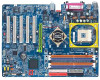
English GA-8IPE1000 Series Motherboard Layout COMA KB_MS R_U SB ATX_12V SOC KET478 Hyper Threading CPU_FAN ATX FDD IDE1 DDR1 GA-8IPE1000 (Pro)(-G) COMB LPT (*u) N A L MIC_IN USB LINE_OUT LINE_IN CD_IN DDR2 DDR3 DDR4 IDE2 F_AU DIO Marv ell * 8 0 0 1 ( u ) NB_FAN (*) Intel® 865PE - Gigabyte GA-8IPE1000 Pro-G | User Manual - Page 13
8 USB (2.0/1.1) Ports ATA33/66/100 IDE Channels Serial ATA Channels 33 M Hz PS/2 KB/M ouse COM Ports PCICLK (33M Hz) USBCLK (48MHz) 14.318 M Hz 33 M Hz 24 M Hz CLK GEN ZCLK (66MHz) CPUCLK+/- (100/133/200MHz) AGPCLK (66MHz) HCLK+/- (100/133MHz) ICH3V66 (66MHz) (*) For GA-8IPE1000 Pro-G only - Gigabyte GA-8IPE1000 Pro-G | User Manual - Page 14
English GA-8IPE1000 Series Motherboard - 10 - - Gigabyte GA-8IPE1000 Pro-G | User Manual - Page 15
steps: Step 1- Install the Central Processing Unit (CPU) Step 2- Install memory modules Step 3- Install expansion cards Step 4- Connect ribbon cables, cabinet with the BIOS/software installation. Note: If the NorthBridge on the motherboard has a fan sink, then the motherboard contains a NB_FAN - Gigabyte GA-8IPE1000 Pro-G | User Manual - Page 16
to 650 Socket Actuation Lever 1. Angling the rod to 65-degree maybe feel a kind of tight, and then continue pull the rod to 90-degree when a noise "cough" made. 2. Pullthe rod to the 90-degree directly. Pin1 indicator Pin1 indicator 3. CPU Top View GA-8IPE1000 Series Motherboard 4. Locate Pin - Gigabyte GA-8IPE1000 Pro-G | User Manual - Page 17
connector, this completes the installation. Please refer to CPUcooling fanuser's manualfor more detailinstallation procedure. 1. Fasten the cooling fan supporting-base onto the CPU socket on the mainboard. 2. Make sure the CPU fan is plugged to the CPU fan connector, than install complete. - 13 - Gigabyte GA-8IPE1000 Pro-G | User Manual - Page 18
(DIMM) sockets. The BIOS will automatically dete cts me mory type and size. To install the memo ry mod ule, just push it vertically into the DIMM socket. The DIMM module can only fit in one direction due to the no tch. Me mory size can vary between sockets. Notch DDR GA-8IPE1000 Series supports the - Gigabyte GA-8IPE1000 Pro-G | User Manual - Page 19
into the DIMMs with the same color in order for Dual Channel Technology to work. The following tables include all memory-installed combination types: (Please note that those types not in the tables will not boot up.) l Figure 1: Dual Channel Technology (DS: Double Side, SS: Single Side) DIMM - Gigabyte GA-8IPE1000 Pro-G | User Manual - Page 20
of 3.2GB/ s of DDR400 memory and complete line of DDR400/333/266/200 memory solutions, DDR memory is the best choice for build ing high performance and low latency DRAM subsystem that are suitable for servers, workstations, and full rang e of de sktop PCs. GA-8IPE1000 Series Motherboard - 16 - - Gigabyte GA-8IPE1000 Pro-G | User Manual - Page 21
slot bracket of the expansion card. 6. Replace your computer's chassis cover. 7. Power on the computer, if necessary, setup BIOS utility of expansion card from BIOS. 8. Install related driver from the operating system. AGP Card Please carefully pull outthe small white- drawable bar at the end of - Gigabyte GA-8IPE1000 Pro-G | User Manual - Page 22
r OS supports USB controller. If your OS doe s not supp ort USB con troller, please contact OS vendor for possible patch or driver upgrade. F or more information please contact your OS or device(s) vendors. LAN connector is fast Eth ernet with 10/100/ 1000 Mbps speed. (*) For GA-8IPE1000 Pro-G only - Gigabyte GA-8IPE1000 Pro-G | User Manual - Page 23
(COMA/COMB) Parallel Port (25 pin Female) This connector supports 2 standard COM ports and 1 Parallel port. Device like Port (9 pin Male) y Audio Connectors Line In(Rear Speaker) Line Out(Front Speaker) MIC In(Center and Subwoofer) After install onboard audio driver, you may connect speaker to - Gigabyte GA-8IPE1000 Pro-G | User Manual - Page 24
F_USB1/F_USB2 18) GAME 19) INFO_LINK 20) F 2 _ 1 3 9 4 (*) 21) F 1 _ 1 3 9 4 (*) 22) SATA0/SATA1 23) CI 24) CLR_CMOS (*) For GA-8IPE1000 Pro-G only. Note: If the NorthBridge on the motherboard has a fan sink, then the motherboard contains a NB_FAN connector. GA-8IPE1000 Series Motherboard - 20 - - Gigabyte GA-8IPE1000 Pro-G | User Manual - Page 25
English 1) ATX_12V (+12VPower Connector) This connector (ATX _12V) suppliesthe CPU operation voltage (Vcore). If this " ATX_ 12V connector" is not connected, system cannotboot. PinNo. Definition 2 1 1 GND 4 3 2 GND 3 +12V 4 +12V 2) ATX (ATX Power) AC power cord should only be connected to - Gigabyte GA-8IPE1000 Pro-G | User Manual - Page 26
supports Max. current up to 600 mA. PinNo. Definition 1 GND 1 2 +12V 3 Sense 4) SYS_FAN (System FAN Connector) This connector allows you to link with the cooling fan on the system case to lower the system temperature. PinNo. Definition 1 GND 1 2 +12V 3 Sense GA-8IPE1000 Series Motherboard - Gigabyte GA-8IPE1000 Pro-G | User Manual - Page 27
Fan will not work. Sometimes will damage the Chip Fan. (Usually black cable is GND) Note: If the NorthBridge on the motherboard has a fan sink, then the motherboard contains a NB_FAN connector. PinNo. Definition 1 1 VCC 2 GND (*) For GA-8IPE1000 Pro-G only. - 23 - Hardware Installation Process - Gigabyte GA-8IPE1000 Pro-G | User Manual - Page 28
the Pin1. 40 39 2 1 8) FDD (Floppy Connector) Please connect the floppy drive ribbon cables to FDD. Itsupports 360K,720K,1.2M,1.44M and 2.88Mbytes floppy disk types. The red stripe of the ribbon cable must be the same side with the Pin1. 34 33 2 1 GA-8IPE1000 Series Motherboard - 24 - - Gigabyte GA-8IPE1000 Pro-G | User Manual - Page 29
CAUTION v Danger of explosion if battery is incorrectly replaced. v Replace only with the same or equivalent type recommended by the manufacturer. v Dispose of used batteries according to the manufacturer's instructions. If you want to erase CM OS... 1.Turn OFF the computer and unplug the power cord - Gigabyte GA-8IPE1000 Pro-G | User Manual - Page 30
(+) Pin 2- Pin 3: NC Pin 4: Data(-) Open:Normal Operation Close: Reset Hardware System Open:Normal Operation Close:Power On/Off Pin 1: LED anode(+) Pin2: LEDcathode(-) NC GA-8IPE1000 Series Motherboard - 26 - - Gigabyte GA-8IPE1000 Pro-G | User Manual - Page 31
on the MB header. To find out if the chassis you are buying support front audio connector, please contact your dealer.Please note, you can have the alternative of using front audio connector or of using rear audio connector to play sound. 12 9 10 Pin No. 1 2 3 4 5 6 7 8 9 10 Definition MIC GND - Gigabyte GA-8IPE1000 Pro-G | User Manual - Page 32
GND 4 CD_R 15) SPDIF_IO (SPDIF In/Out) The SPDIF output is capable of providing digital audio to external speakers or compressed AC3 data to an external Dolby Digital Decoder. Use this feature only . 1 2 3 4 5 6 Definition VCC No Pin SPDIF SPDIFI GND GND GA-8IPE1000 Series Motherboard - 28 - - Gigabyte GA-8IPE1000 Pro-G | User Manual - Page 33
cable, incorrect connection between the cable and connector will make the device unable to wor k or even dam age it. For optional front USB cable, please contact your local dealer. 2 10 19 Pin No. 1 2 3 4 5 6 7 8 9 10 Definition Power Power USB0 DX-/USB6 DXUSB1 Dy-/USB7 DyUSB0 DX+/USB6 DX+ USB1 - Gigabyte GA-8IPE1000 Pro-G | User Manual - Page 34
English 18) GAME (GAME Connector) This connector supports joystick, MIDI keyboard and other relate audio devices. Pin No. Definition 1 VCC 2 GRX1_R 3 GND 4 GPSA2 5 VCC 2 16 7 8 9 10 Definition SMBCLK VCC SMBDATA GPIO GND GND No Pin NC +12V +12V GA-8IPE1000 Series Motherboard - 30 - - Gigabyte GA-8IPE1000 Pro-G | User Manual - Page 35
. For optional IEEE1394 cable, please contact your local dealer. 2 10 19 Pin No. 1 2 3 4 5 6 7 8 9 10 Definition T PA2+ T PA2GND GND TPB2+ TPB2Power Power No Pin GND (*) For GA-8IPE1000 Pro-G only. - 31 - Hardware Installation Process - Gigabyte GA-8IPE1000 Pro-G | User Manual - Page 36
TXP TXN GND RXN RXP GND 23) CI (CASE OPEN) This 2 pin connector allows your system to enable or disable the "case open" item in BIOS if the system casebegin remove. PinNo. Definition 1 1 Signal 2 GND GA-8IPE1000 Series Motherboard - 32 - - Gigabyte GA-8IPE1000 Pro-G | User Manual - Page 37
English 24) CLR_CMOS (Clear CMOS) You may clear the CMOS data to its default values by this jumper. To clear CMOS, temporarily shor 1-2 pin. Default doesn't include the "Shunter" to prevent from improper use this jumper. 1 Open: Normal 1 Short: Clear CMOS - 33 - Hardware Installation Process - Gigabyte GA-8IPE1000 Pro-G | User Manual - Page 38
English GA-8IPE1000 Series Motherboard - 34 - - Gigabyte GA-8IPE1000 Pro-G | User Manual - Page 39
for Option Page Setup Menu Load the file-safe default CMOS value from BIOS default table Load the Optimized Defaults Dual BIOS (*)/Q-Flash function System Information Save all the CMOS changes, only for Main Menu (*) For GA-8IPE1000 Pro-G only. - 35 - BIOS Setup - Gigabyte GA-8IPE1000 Pro-G | User Manual - Page 40
exit the Help Window press . The Main Menu (For example: BIOS Ver.: 8IPE1000 Pro-G.E1) Once you enterAward BIOS CMOS Setup BIOS. l Advanced BIOS Features This setup page includes all the items of Award special enhanced features. (*) For GA-8IPE1000 Pro-G only. GA-8IPE1000 Series Motherboard - Gigabyte GA-8IPE1000 Pro-G | User Manual - Page 41
system. l Save & Exit Setup Save CMOS value settings to CMOS and exit setup. l Exit Without Saving Abandon all CMOS value changes and exit setup. (*) For GA-8IPE1000 Pro-G only. - 37 - BIOS Setup - Gigabyte GA-8IPE1000 Pro-G | User Manual - Page 42
Mode Support Halt On Base Memory Ex tended Memory Total Memory BIOS and is display only Month The month, Jan. Through Dec. Day The day , from 1 to 31 (or the max imum allow ed in the month) Year The y ear, from 1999 through 2098 (*) For GA-8IPE1000 Pro-G only. GA-8IPE1000 Series Motherboard - Gigabyte GA-8IPE1000 Pro-G | User Manual - Page 43
types: auto type, and manual type. Manual type is user-definable; Auto type which will automatically detect HDD type. Note that the specifications of your drive must match with the drive table. The hard disk . 2.88M, 3.5 in. 3.5 inch double-sided driv e; 2.88M by te capacity . - 39 - BIOS Setup - Gigabyte GA-8IPE1000 Pro-G | User Manual - Page 44
K memory installed on the motherboard, or 640 K for systems with 640 K or more memory installed on the motherboard. Extended Memory The BIOS determines how much extended memory is present during the POST. This is the amount of memory located above 1 MB in the CPU's memory address map. GA-8IPE1000 - Gigabyte GA-8IPE1000 Pro-G | User Manual - Page 45
dev ice priority by Hard Disk. CDROM Select y our boot dev ice priority by CDROM. ZIP Select y our boot dev ice priority by ZIP. USB-FDD Select y our boot dev ice priority by USB-FDD. USB-ZIP Select y our boot dev ice priority by USB-ZIP. (*) For GA-8IPE1000 Pro-G only. - 41 - BIOS Setup - Gigabyte GA-8IPE1000 Pro-G | User Manual - Page 46
. (Default v alue) CPU Hyper-Threading Enabled Enables CPU Hy per Threading Feature. Please note that this feature is only w orking for operating sy stem w ith multi processors mode supported. (Default v alue) Disabled Disables CPU Hy per Threading. GA-8IPE1000 Series Motherboard - 42 - - Gigabyte GA-8IPE1000 Pro-G | User Manual - Page 47
/PD:Value F10:Sav e ESC:Ex it F1:General Help * F 3 : L a n g u a g e ( ) F5:Prev ious Values F6:Fail-Safe Defaults F7:Optimized Defaults Figure 4: Integrated Peripherals (*) For GA-8IPE1000 Pro-G only. (u) For GA-8IPE1000-G only. - 43 - BIOS Setup - Gigabyte GA-8IPE1000 Pro-G | User Manual - Page 48
(Default Value) Set SATA Mode manually. SATA Port0 Configure as IDE Pri support by WinXP or later OS only . SATA Port1 Configure as The v alues depend on SATA Port0. USB Controller Enabled Enable USB Controller. (Default v alue) Disabled Disable USB Controller. GA-8IPE1000 Series Motherboard - Gigabyte GA-8IPE1000 Pro-G | User Manual - Page 49
is 3F8. (Default v alue) 2F8/IRQ3 Enable onboard Serial port 1 and address is 2F8. 3E8/IRQ4 Enable onboard Serial port 1 and address is 3E8. (*) For GA-8IPE1000 Pro-G only. (u) For GA-8IPE1000-G only. - 45 - BIOS Setup - Gigabyte GA-8IPE1000 Pro-G | User Manual - Page 50
onboard Serial port 1 and address is 2E8. Disable onboard Serial port 1. Onboard Serial Port 2 Auto BIOS w ill automatically setup the port 2 address. 3F8/IRQ4 Enable onboard Serial port 2 and address is Port. ECP+EPP Using Parallel port as ECP & EPP mode. GA-8IPE1000 Series Motherboard - 46 - - Gigabyte GA-8IPE1000 Pro-G | User Manual - Page 51
320. Disabled Disable this function. (Default Value) CIR Port IRQ 5 Set CIR Port IRQ to 5. 11 Set CIR Port IRQ to 11. (Default Value) - 47 - BIOS Setup - Gigabyte GA-8IPE1000 Pro-G | User Manual - Page 52
( ) F5:Prev ious Values F6:Fail-Safe Defaults F7:Optimized Defaults Figure 5: Pow er Management Setup ACPI Suspend Type S1(POS) Set ACPI suspend ty pe to S1. (Default Value) S3(STR) Set ACPI suspend ty pe to than 4 sec. (*) For GA-8IPE1000 Pro-G only. GA-8IPE1000 Series Motherboard - 48 - - Gigabyte GA-8IPE1000 Pro-G | User Manual - Page 53
WakeOnLAN Disabled Disable Modem Ring on/w ake on Lan function. Enabled Enable Modem Ring on/w ake on Lan. (Default Value) Resume by Alarm You Enter to set the Key - board Pow er On Passw ord. AC BACK Function Memory Sy stem pow er on depends on the status before AC lost. Soft-Off Alw - Gigabyte GA-8IPE1000 Pro-G | User Manual - Page 54
4 IRQ Assignment Auto Auto assign IRQ to PCI 4. (Default v alue) 3,4,5,7,9,10,11,12,14,15 Set IRQ 3,4,5,7,9,10,11,12,14,15 to PCI 4. (*) For GA-8IPE1000 Pro-G only. GA-8IPE1000 Series Motherboard - 50 - - Gigabyte GA-8IPE1000 Pro-G | User Manual - Page 55
computer w ill res tart. Current Voltage (V) Vcore / DDR25V / +3.3V / +5V / +12V Detect sy stem's v oltage status automatically . Current CPU Temperature Detect CPU Temp. automatically. (*) For GA-8IPE1000 Pro-G only. - 51 - BIOS Setup - Gigabyte GA-8IPE1000 Pro-G | User Manual - Page 56
fan w ill run at medium speed. d. When the CPU temperature is low er than 40 degrees Celsius, CPU fan w ill run at low speed. (*) For GA-8IPE1000 Pro-G only. GA-8IPE1000 Series Motherboard - 52 - - Gigabyte GA-8IPE1000 Pro-G | User Manual - Page 57
MenuLevelu øCPU Host Frequency (Mhz) 100 øAGP/PCI/SRC Fix ed 66/33/100 Memory Frequency For [Auto] Memory Frequency (Mhz) 266 AGP/PCI/SRC Frequency (Mhz) 66/33/100 AGP Ov erVoltage " and read only if the CPU ratio is not changeable. (*) For GA-8IPE1000 Pro-G only. - 53 - BIOS Setup - Gigabyte GA-8IPE1000 Pro-G | User Manual - Page 58
data. (Default v alue) for FSB(Front Side Bus) frequency =800MHz, 2.0 Memory Frequency = Host clock X 2.0. 1.6 Memory Frequency = Host clock X 1.5. 1.33 Memory Frequency = Host clock X 1.33. Auto Set Memory frequency by DRAM SPD data. (Default v alue) GA-8IPE1000 Series Motherboard - 54 - - Gigabyte GA-8IPE1000 Pro-G | User Manual - Page 59
English Memory Frequency(Mhz) The v alues depend on CPU Host Frequency (Mhz). AGP/PCI Ov erVoltage Control to +0.2V. +0.3V Set DIMM Ov erVoltage Control to +0.3V. CPU Voltag e Control Supports adjustable CPU Vcore from 0.8375V to 1.7600V. (Default v alue: Normal) Normal CPU Vcore Display y our CPU - Gigabyte GA-8IPE1000 Pro-G | User Manual - Page 60
F8: Dual BIOS (*)/Q-Flash F10:Sav e & Ex it Setup Figure 9: Select Language Select Language Multi Language supports 7 languages. There are English, Japanese, French, Spanish, German, Simplified Chinese, Traditional Chinese. (*) For GA-8IPE1000 Pro-G only. GA-8IPE1000 Series Motherboard - 56 - - Gigabyte GA-8IPE1000 Pro-G | User Manual - Page 61
e ( ) F8: Dual BIOS (*)/Q-Flash F10:Sav e & Ex it Setup Load Fail-Safe Defaults Figure 10: Load Fail-Safe Defaults Load Fail-Safe Defaults Fail-Safe defaults contain the most appropriate values of the system parameters that allow minimum system performance. (*) For GA-8IPE1000 Pro-G only. - 57 - Gigabyte GA-8IPE1000 Pro-G | User Manual - Page 62
F10:Sav e & Ex it Setup Load Optimized Defaults Figure 11: Load Optimized Defaults Load Optimized Defaults Selecting this field loads the factory defaults for BIOS and Chipset Features which the system automatically detects. (*) For GA-8IPE1000 Pro-G only. GA-8IPE1000 Series Motherboard - 58 - - Gigabyte GA-8IPE1000 Pro-G | User Manual - Page 63
Advance BIOS Features Menu, you will be prompted for the password every time the system is rebooted or any time you try to enter Setup Menu. If youselect "Setup" at "Password Check" inAdvance BIOS Features Menu, you will be prompted only when you try to enter Setup. (*) For GA-8IPE1000 Pro-G only - Gigabyte GA-8IPE1000 Pro-G | User Manual - Page 64
( ) F8: Dual BIOS (*)/Q-Flash F10:Sav e & Ex it Setup Sav e Data to CMOS Figure 13: Sav e & Ex it Setup Type "Y" will quit the Setup Utility and save the user setup value to RTC CMOS. Type "N" will return to Setup Utility. (*) For GA-8IPE1000 Pro-G only. GA-8IPE1000 Series Motherboard - 60 - - Gigabyte GA-8IPE1000 Pro-G | User Manual - Page 65
* F 3 : C h a n g e L a n g u a g e ( ) F8: Dual BIOS (*)/Q-Flash F10:Sav e & Ex it Setup Abandon all Data Figure 14: Ex it Without Sav ing Type "Y" will quit the Setup Utility without saving to RTC CMOS. Type "N" will return to Setup Utility. (*) For GA-8IPE1000 Pro-G only. - 61 - BIOS Setup - Gigabyte GA-8IPE1000 Pro-G | User Manual - Page 66
English GA-8IPE1000 Series Motherboard - 62 - - Gigabyte GA-8IPE1000 Pro-G | User Manual - Page 67
the BIOS source code correctly in your disks as if you update the wrong BIOS, it will be a nightmare. Certainly,you wonder why motherboard vendors could notjust do something rightto save your time and effort and save you from the lousy BIOS updating work? Here it comes! Now Gigabyte announces @BIOS - Gigabyte GA-8IPE1000 Pro-G | User Manual - Page 68
byEasyTune 4. Please find the products supported list in the web site. *Any "Overclocking action" is at u ser's risk, Gig abyte Technolo gy will not be responsible for any damage or instability to your processor, motherboard, or any other components. GA-8IPE1000 Series Motherboard - 64 - - Gigabyte GA-8IPE1000 Pro-G | User Manual - Page 69
compatible picture you prefer into BIOS.And not only this, FaceWizardTM also helps userto update BIOSin windows mode. What's benefit for "Next". (2) 4.Click "Start"-"Programs"-"GIGABYTE UTILITY"-"Face-Wizard". (4) 5.Click "Help". (5) (*) For GA-8IPE1000 Pro-G only. - 65 - Technical Reference - Gigabyte GA-8IPE1000 Pro-G | User Manual - Page 70
}PC Health Status Save & Exit Setup }Frequency/Voltage Control Exit Without Saving ES C:Qu it * F 3 : C h a n g e L a n g u a g e ( ) F8: Dual BIOS (*)/Q-Flash F10:Save & Exit Setup Tim e, Date, Hard Disk Type... (*) For GA-8IPE1000 Pro-G only. GA-8IPE1000 Series Motherboard - 66 - - Gigabyte GA-8IPE1000 Pro-G | User Manual - Page 71
Backup ROM Type/Size SST49LF003A WideRangeProtection Disable BootFrom Main Bios Auto Recovery Enable Halt On Error Disable Keep DMI Data Enable Copy Main ROM Data to Backup Load DefaultSettings Save Settings to CMOS Q-Flash Utility Update Main BIOS from Floppy Update Backup BIOS from - Gigabyte GA-8IPE1000 Pro-G | User Manual - Page 72
the Backup BIOS works normally and could automatically recover the Main BIOS. (This auto recovery utility is setby system automatically and can'tbe changed by user.) Load Default Settings Load dual BIOS default value. Save Settings to CMOS Save revised setting. GA-8IPE1000 Series Motherboard - 68 - Gigabyte GA-8IPE1000 Pro-G | User Manual - Page 73
this innovation. What's DualBIOSTM? On GIGABYTE motherboards with DualBIOS there are physically two BIOS chips. For simplicity we'll call one your "Main BIOS" and the other we'll call your "Backup" BIOS (your "hot spare"). If your Main BIOS fails, the Backup BIOS almost automatically takes over on - Gigabyte GA-8IPE1000 Pro-G | User Manual - Page 74
a one-way flash utility. The built-in one-way flash utility will ensure that the corruptBIOS is not mistaken as the good BIOS during recovery and thatthe correct BIOS (main vs. backup) will be flashed. This will prevent the good BIOS from being flashed. GA-8IPE1000 Series Motherboard - 70 - - Gigabyte GA-8IPE1000 Pro-G | User Manual - Page 75
.) A user may override booting from the main system BIOS. The DualBIOSTM utility maybe entered to manually change the boot sequence to bootfrom the backup BIOS. 2. During or after a BIOS upgrade, if DualBIOSTM detects that the main BIOS is corrupt, the backup BIOS will take over the boot-up process - Gigabyte GA-8IPE1000 Pro-G | User Manual - Page 76
.F12) to a floppydisk. 3. Rebootyour PC and press Del to enter BIOS menu. The BIOS upgrading guides below are separated into two parts. If your motherboard has dual BIOS, please refer to Part One. If your motherboard has single BIOS, please refer to Part Two. GA-8IPE1000 Series Motherboard - 72 - - Gigabyte GA-8IPE1000 Pro-G | User Manual - Page 77
English Part One: Updating BIOS with Q-Flash™ Utility on Dual BIOS Motherboards. Some of Gigabyte motherboards are equipped with dual BIOS. In the BIOS menu of the motherboards supporting Q-Flash™ and Dual BIOS, the Q-Flash™ utility and Dual BIOS utility are combined in the same screen. This - Gigabyte GA-8IPE1000 Pro-G | User Manual - Page 78
Q-Flash Utility Load M ain BIO S from Floppy Load Backup BI OS from Floppy Sav e Main BIOS to Floppy Sav e Backup B IOS to Floppy Enter : Run hi:Mov e ES C:Reset Dual BIOS utility bar 256K 256K Q-FlashTM utility title bar F10:Power Off Action bar GA-8IPE1000 Series Motherboard - 74 - - Gigabyte GA-8IPE1000 Pro-G | User Manual - Page 79
these actions. Using the Q-Flash™ utility: This section tells you how to update BIOS using the Q-Flash™ utility.As described in the "Before you begin" section above, you must prepare a floppy disk having the BIOS file for your motherboard and insert it to your computer. If you have already put the - Gigabyte GA-8IPE1000 Pro-G | User Manual - Page 80
Load Backup BI OS from Floppy Sav e Main BIOS to Floppy Sav e Backup B IOS to Floppy hi:Mov e ES C:Reset F10:Power Off Do not truning off power or reset your system at this stage!! Please do not take out the floppy disk when it begins flashing BIOS. GA-8IPE1000 Series Motherboard - 76 - - Gigabyte GA-8IPE1000 Pro-G | User Manual - Page 81
3. Press Ybutton on yourkeyboard after you are sure to update BIOS. Then it will begin to update BIOS. The progress of updating BIOS will be displayed. Dual BIOS Utility Boot From Main Bios Main ROM Type/Size S ST 49LF003A Backup ROM Type/S ize S ST 49LF003A Wide Range Protection Disable Boot - Gigabyte GA-8IPE1000 Pro-G | User Manual - Page 82
Default S ettings [E nter]StaovceoSnteinttuinegsorto[ECsMcO] tSo abort. .. Q-Flash Utility Load M ain BIO S from Floppy Load Backup BI OS from Floppy Sav e Main BIOS to Floppy Sav e Backup B IOS to Floppy Enter : Run hi:Mov e ES C:Reset F10:Power Off GA-8IPE1000 Series Motherboard - 78 - - Gigabyte GA-8IPE1000 Pro-G | User Manual - Page 83
system reboots, you may find the BIOS version on your boot screen becomes the one you flashed. The BIOS file becomes F12after updating Ame r ican R el e ase :0 8 /2 3/2 00 2 Meg a tre n d s AMIBIOS ( C) 19 9 9 Ame ri ca n Me ga tr en d 7VRXP F1 2 AMD- Ath lo n(tm) Pro ce sso r- 133 3MHz Ch eck - Gigabyte GA-8IPE1000 Pro-G | User Manual - Page 84
to CMOS and exitthe BIOS menu. System willrebootafteryou exitthe BIOS menu. The procedure is completed. AMIBIOS SIMPLE SETUP UTILITY - VERSION 2.00 (C ) 2001 afe V alues F7: O ptimized V alues F8: Dual BIOS/Q-Flash F10:Sav e & Exit Load Fail-Safe Defaults GA-8IPE1000 Series Motherboard - 80 - - Gigabyte GA-8IPE1000 Pro-G | User Manual - Page 85
Updating BIOS with Q-Flash™ Utility on Single-BIOS Motherboards. This part guides users ofsingle-BIOS motherboards how to update BIOS using the Q-Flash™ utility. Entering the Q-Flash™ utility: Step1: To use the Q-Flash™ utility, you mustpress Del in the bootscreen to enter BIOS , Hard Disk Type. .. - Gigabyte GA-8IPE1000 Pro-G | User Manual - Page 86
BIOS for backup purpose, you can begin Step 1 with Save Main BIOS to Floppy item. Q-Flash Utility V1.30 Flash Ty pe/ Size SST 49LF002A 256K Keep DMI DataE nable Update B IOS from Floppy Save BIOS to Floppy Enter: Run h/i: M ove E SC: Reset F10: Power Off GA-8IPE1000 Series Motherboard - Gigabyte GA-8IPE1000 Pro-G | User Manual - Page 87
a box showing the BIOS files you downloaded to the floppy disk. In this example, we only download one BIOS for this board, 8GE800 the correct BIOS file for your motherboard. Q-Flash Utility V1.30 Flash Ty pe/ Size SST 49LF002A 256K Keep DMI DataE nable Update B IOS from Floppy Save BIOS to - Gigabyte GA-8IPE1000 Pro-G | User Manual - Page 88
E SC: Reset F10: Power Off 6. Press Del to enter BIOS menu after system reboots and load BIOS Fail-Safe Defaults. See how to load BIOS Fail-Safe Defaults, please kindly refer to Step 6 to 7 in Part One. Congratulation!! You have updated BIOS successfully!! GA-8IPE1000 Series Motherboard - 84 - - Gigabyte GA-8IPE1000 Pro-G | User Manual - Page 89
Click "OK". (3) (4) Methods and steps: I. Update BIOS through Internet a. Click "Internet Update" icon b. Click "Update New BIOS" icon c. Select @BIOSTM sever d. Selectthe exactmodelname on your motherboard e. System will automatically download and update the BIOS. - 85 - Technical Reference - Gigabyte GA-8IPE1000 Pro-G | User Manual - Page 90
, downloading from internetor anyother methods (such as: 8IPE1000 Pro-G.F1). e. Complete update processfollowing the instruction. III. Save BIOS In the very beginning, there is "Save Current BIOS" icon shown in dialog box.It means to save the current BIOS version. IV. Check outsupported motherboard - Gigabyte GA-8IPE1000 Pro-G | User Manual - Page 91
4- / 6- / 8- Channel Audio Function Introduction The installation of windows 98SE/2K/ME/XP is very simple. Please follow next the stereo speakers or earphone to "Line Out". STEP 2 : Following installation of the audio driver, you find a icon a Sound Effect icon on the lower right hand taskbar. Click - Gigabyte GA-8IPE1000 Pro-G | User Manual - Page 92
to "Line Out", the rear channels to "Line In". STEP 2 : Following installation of the audio driver, you find a icon a Sound Effect icon on the lower right hand taskbar. Click the icon to and select "4CH Speaker" to com plete 4 channel audio configuration. GA-8IPE1000 Series Motherboard - 88 - - Gigabyte GA-8IPE1000 Pro-G | User Manual - Page 93
Line Out",the rear channels to "Line In", and the Center/Subwoofer channels to "MIC In". M IC In Line Out STEP 2 : Following installation of the audio driver, you find a icon a Sound Effect icon on the lower right hand taskbar. Click the icon to select the function. Line In STEP 3 : Click "Speaker - Gigabyte GA-8IPE1000 Pro-G | User Manual - Page 94
the front channels to the "LINE OUT" port located on the audio panel and the rear channels to the Surround-Kit "REAR R/L" port. Connect the center/subwoofer channels to the Surround-Kit "SUB CENTER" and the R/L channels to the Surround-Kit "SUR BACK" port. GA-8IPE1000 Series Motherboard - 90 - - Gigabyte GA-8IPE1000 Pro-G | User Manual - Page 95
panel and the R/L channels to the Surround-Kit "SUR BACK" port. (This m ethod requires UAJ function) STEP 4 : Following installation of the audio driver, you find a icon a Sound Effect icon on the lower right hand taskbar. Click the icon to select the function. STEP 5 : Click "Speaker Configuration - Gigabyte GA-8IPE1000 Pro-G | User Manual - Page 96
SPDIF Output Device (Optional Device) A "SPDIF output" device is available on the motherboard. Cable with rear bracket is provided and could link to the "SPDIF output" 2. Connect SPDIF device to the m otherboard. 3. Connect SPDIF to the SPDIF decoder. GA-8IPE1000 Series Motherboard - 92 - - Gigabyte GA-8IPE1000 Pro-G | User Manual - Page 97
-detection function. Install Microsoft DirectX8.1 or later version before to enable Jack-Sensing support for Windows 98/9 8SE/2000 /M E. Jack-Sensing includes 2 parts: AUTO and MANUAL. Following is an example for 2 channels (Windows XP): Introduction of audio connectors You may connect CDROM , Walkm - Gigabyte GA-8IPE1000 Pro-G | User Manual - Page 98
Line-in/ Line-out). That m eans users do not need to worry the audio device should be plug in Line-in or Line-out jack, the device will work perfectly after UAJ is a ctiv ated . Enable UAJ function: You can click "UAJ Autom atic" button to enable UAJ function. GA-8IPE1000 Series Motherboard - 94 - - Gigabyte GA-8IPE1000 Pro-G | User Manual - Page 99
you to install one O.S . 4. It mustbe used with IDE hard disk supporting HPA . 5. The firstpartition mustbe setas the bootpartition. When the bootpartition go to "Advanced BIOS" setting menu and setboot from CD-ROM , then save and exit the BIOS menu . Later,please insertMB driver CD into your drive - Gigabyte GA-8IPE1000 Pro-G | User Manual - Page 100
. GIGABYTE TechnilogyCO. , Ltd. 1. Execute Backup Utility 2. Execute Restore Utility 3. Remove Backup Im age 4. Exit and Restart If you ever entered Xpress Recovery by booting from CD-ROM, you'll still be directed to BMP mode by pressing F9 in the bootup screen. GA-8IPE1000 Series Motherboard - 96 - Gigabyte GA-8IPE1000 Pro-G | User Manual - Page 101
English 1.Execute Backup Utility: ! Press B to Backup your System or Esc to Exit The Backup utility will scan the system automatically and back up it. The backed up data willbe saved as an hidden image . 2.Execute Restore Utility: ! This program will recover your system to factory default. Press R - Gigabyte GA-8IPE1000 Pro-G | User Manual - Page 102
English GA-8IPE1000 Series Motherboard - 98 - - Gigabyte GA-8IPE1000 Pro-G | User Manual - Page 103
Drivers Pictures below are shown in Windows XP Insert the driver CD-title that came with your motherboard into your CD-ROM drive, the driver CD-title will auto start and show the installation guide driver manually or switch to the to install the drivers automatically. Massage: Some device drivers - Gigabyte GA-8IPE1000 Pro-G | User Manual - Page 104
LAN chip use. n RealTek AC97 Codec Driver For Intel(R) ICH/ICH2/ICH4/ICH5 AC97 audio. n Intel USB 2.0 Driver It is recommended that you use the Microsoft Windows update for the most updated driver for XP/2K. For USB2.0 driver support under Windows XP operating system, please use Windows Service - Gigabyte GA-8IPE1000 Pro-G | User Manual - Page 105
9 to enable 3D hardware acceleration that support for operating system to achieve better 3D performence. n Marvell VCT Utility (*u) Utility for Marvell chips. [VCT(Virtual Cable Tester) Technology for Gigabit Networks] (*) For GA-8IPE1000 Pro-G only. (u) For GA-8IPE1000-G only. - 101 - Appendix - Gigabyte GA-8IPE1000 Pro-G | User Manual - Page 106
English SOFTWARE INFORMATION This page list the contects of softwares and drivers in this CD title. HARDWARE INFORMATION This page lists all device you have for this motherboard. CONTACT US Please see the last page for details. GA-8IPE1000 Series Motherboard - 102 - - Gigabyte GA-8IPE1000 Pro-G | User Manual - Page 107
disk before installing drivers. You also need to go through some rather different steps in the installation process. Therefore, we suggest that you refer to the installation steps in the RAID manual at our website. (Please download it at http://tw.giga-byte.com/support/user_pdf/raid_manual.pdf - Gigabyte GA-8IPE1000 Pro-G | User Manual - Page 108
manual and check whether you have connected any cable that is not provided with the motherboard package to the USB Over Current pin in the Front USB Panel. If the cable is your own cable, please remove it from this pin and do not connect any of your own cables to it. GA-8IPE1000 Series Motherboard - Gigabyte GA-8IPE1000 Pro-G | User Manual - Page 109
to case. gAMI BIOS Beep Codes *Computer gives 1 short beep when system boots successfully. *Except for beep code 8, these codes are always fatal. 1 beep Refresh failure 2 beeps Parity error 3 beeps Base 64K memory failure 4 beeps Timer not operational 5 beeps Processor error 6 beeps 8042 - gate A20 - Gigabyte GA-8IPE1000 Pro-G | User Manual - Page 110
SCSI/ RAID card ? Answer:Please set in the BIOS as follow: 1. Advanced BIOS features-->(SATA)/RAID/SCSI boot order: "SCSI" 2. Advanced BIOS features--> First boot device: "SCSI" Then it depends on the mode(RAID or ATA) that you need to set in RAID/ SCSI BIOS. GA-8IPE1000 Series Motherboard - 106 - - Gigabyte GA-8IPE1000 Pro-G | User Manual - Page 111
trouble during boot up, please follow the troubleshooting procedures . START Turn off the power and unplug the AC power cable, then remove all of the add-on cards and cables from motherboard. Please make sure motherboard CPU_FAN properly? Yes Check if the memory install properly into the DIMM slot. - Gigabyte GA-8IPE1000 Pro-G | User Manual - Page 112
your problem, please contact with your local retailer or national distributor for help. Or, you could submit your question to the service mail via Gigabyte website technical support zone (http://www.gigabyte.com.tw). The appropriate response will be provided ASAP. GA-8IPE1000 Series Motherboard - Gigabyte GA-8IPE1000 Pro-G | User Manual - Page 113
Number: BIOS version: O.S./A.S.: Hardware Mfs. Model name Size: Configuration CPU Memory Brand Video Card Audio Card HDD CD-ROM / DVD-ROM Modem Network AMR / CNR Keyboard Mouse Power supply Other Device Phone No.: PCB revision: Driver/Utility: Problem Description: & - 109 - Gigabyte GA-8IPE1000 Pro-G | User Manual - Page 114
System Configuration Data Error Checking and Correcting Electromagnetic Compatibility Enhanced Parallel Port Electrostatic Discharge Floppy Disk Device Front Side Bus Hard Disk Device Integrated Dual Channel Enhanced Interrupt Request to be continued...... GA-8IPE1000 Series Motherboard - 110 - - Gigabyte GA-8IPE1000 Pro-G | User Manual - Page 115
Acronyms IOAPIC ISA LAN I/O LBA LED Memory Translator Hub Memory Protocol Translator Network Interface Card Operating System Original Equipment Manufacturer PCI A.G.P. Controller Power-On Self Test Peripheral Component Interconnect Rambus in-line Memory Module Special Circumstance Instructions - Gigabyte GA-8IPE1000 Pro-G | User Manual - Page 116
English GA-8IPE1000 Series Motherboard - 112 - - Gigabyte GA-8IPE1000 Pro-G | User Manual - Page 117
- 113 - Memo English - Gigabyte GA-8IPE1000 Pro-G | User Manual - Page 118
English GA-8IPE1000 Series Motherboard - 114 - - Gigabyte GA-8IPE1000 Pro-G | User Manual - Page 119
- 115 - Memo English - Gigabyte GA-8IPE1000 Pro-G | User Manual - Page 120
efficient mail replying service. If you have (626) 854-9339 E-mail: [email protected] [email protected] WEB Address: gigabyte.com.cn WEB Address: http://cn.giga-byte.com Chengdu Office Tel: 86-28-85236930 Fax: 86-28-85256822 WEB Address: http://cn.giga-byte.com GA-8IPE1000 Series Motherboard
-
 1
1 -
 2
2 -
 3
3 -
 4
4 -
 5
5 -
 6
6 -
 7
7 -
8
-
9
-
10
-
11
-
12
-
13
-
14
-
15
-
16
-
17
-
18
-
19
-
20
-
21
-
22
-
23
-
24
-
25
-
26
-
27
-
28
-
29
-
30
-
31
-
32
-
33
-
34
-
35
-
36
-
37
-
38
-
39
-
40
-
41
-
42
-
43
-
44
-
45
-
46
-
47
-
48
-
49
-
50
-
51
-
52
-
53
-
54
-
55
-
56
-
57
-
58
-
59
-
60
-
61
-
62
-
63
-
64
-
65
-
66
-
67
-
68
-
69
-
70
-
71
-
72
-
73
-
74
-
75
-
76
-
77
-
78
-
79
-
80
-
81
-
82
-
83
-
84
-
85
-
86
-
87
-
88
-
89
-
90
-
91
-
92
-
93
-
94
-
95
-
96
-
97
-
98
-
99
-
100
-
101
-
102
-
103
-
104
-
105
-
106
-
107
-
108
-
109
-
110
-
111
-
112
-
113
-
114
-
115
-
116
-
117
-
118
-
119
-
120
 |
 |

When you installing AGP card, please make sure the following
notice is fully understood and practiced. If your AGP card has
"AGP 4X/8X (1.5V) notch"(show below), please make sure your
AGP card is AGP 4X/8X (1.5V).
Caution: AGP 2X card is not supported by Intel
®
845(GE/PE) / 845(E/
G) / 850(E) / E7205 / 865(G/PE/P) / 875P. You might experience system
unable to boot up normally. Please insert an AGP 4X/8X card.
Example 1: Diamond Vipper V770 golden finger is compatible with 2X/4X
mode AGP slot. It can be switched between AGP 2X(3.3V) or 4X(1.5V)
mode by adjusting the jumper. The factory default for this card is
2X(3.3V). The GA-8IPE1000 Series (or any AGP 4X/8X only)
motherboards might not function properly, if you install this card without
switching the jumper to 4X(1.5V) mode in it.
Example 2: Some ATi Rage 128 Pro graphics cards made by "Power Color",
the graphics card manufacturer & some SiS 305 cards, their golden finger
is compatible with 2X(3.3V)/4X(1.5V) mode AGP slot, but they support 2X
(3.3V) only. The GA-8IPE1000 Series (or any AGP 4X/8X only)
motherboards might not function properly, If you install this card in it.
Note : Although Gigabyte's AG32S(G) graphics card is based on ATi Rage
128 Pro chip, the design of AG32S(G) is compliance with AGP 4X(1.5V)
specification. Therefore, AG32S(G) will work fine with Intel
®
845(GE/PE) /
845(E/G) / 850(E) / E7205 / 865(G/PE/P) / 875P based motherboards.
Before you install PCI cards, please remove the Dual BIOS label from
PCI slots if there is one.
AGP 4X/8X notch