Gigabyte GA8PE800 User Guide
Gigabyte GA8PE800 Manual
 |
View all Gigabyte GA8PE800 manuals
Add to My Manuals
Save this manual to your list of manuals |
Gigabyte GA8PE800 manual content summary:
- Gigabyte GA8PE800 | User Guide - Page 1
3V)/4X(1.5V) mode AGP slot, but they support 2X(3.3V) only. The GA-8PE800(-L) (or any AGP 4X only) motherboards might not function properly, If you install this card in it. Note : Although Gigabyte's AG32S(G) graphics card is based on ATi Rage 128 Pro chip, the design of AG32S(G) is compliance with - Gigabyte GA8PE800 | User Guide - Page 2
. M Third-party brands and names are the property of their respective owners. M Please do not remove any labels on motherboard, this may void the warranty of this motherboard. M Due to rapid change in technology, some of the specifications might be out of date before publication of this booklet - Gigabyte GA8PE800 | User Guide - Page 3
41, 1F, 20537 Hamburg, Germany declare that the product ( description of the apparatus, system, installation to which it refers) Mother Board GA-8PE800(-L) is in conformity with (reference to the specification under which conformity is declared) in accordance with 89/336 EEC-EMC Directive Limits - Gigabyte GA8PE800 | User Guide - Page 4
of Industry, CA 91748 Phone/Fax No: (818) 854-9338/ (818) 854-9339 hereby declares that the product Product Name: Motherboard Model Number: GA-8PE800(-L) Conforms to the following specifications: FCC Part 15, Subpart B, Section 15.107(a) and Section 15.109 (a),Class B Digital Device Supplementary - Gigabyte GA8PE800 | User Guide - Page 5
GA-8PE800(-L) P4 Titan Motherboard USER'S MANUAL Pentium®4 Processor Motherboard Rev. 1102 12ME-8PE800-1102 - Gigabyte GA8PE800 | User Guide - Page 6
Checklist 4 Chapter 1 Introduction 5 Features Summary 5 GA-8PE800(-L) Motherboard Layout 7 Block Diagram 8 Chapter 2 Hardware Installation Process 10 Step 1: Install the Central Processing Unit (CPU 11 Step 1-1: CPU Installation 11 Step 1-2 : CPU Cooling Fan Installation 12 Step 2: Install - Gigabyte GA8PE800 | User Guide - Page 7
Set Supervisor/User Password 54 Save & Exit Setup 55 Exit Without Saving 56 Chapter 4 Technical Reference 59 @ BIOSTM Introduction 59 Easy TuneTM 4 Introduction 60 Flash BIOS Method Introduction 61 2-/4-/6-Channel Audio Function Introuction 76 Chapter 5 Appendix 83 - 3 - Table of Content - Gigabyte GA8PE800 | User Guide - Page 8
GA-8PE800 or GA-8PE800-L motherboard þ IDE cable x 1/ Floppy cable x 1 þ CD for motherboard driver & utility þ GA-8PE800(-L) user's manual þ I/O Shield * þ Quick PC Installation Guide o RAID Manual þ 2 Port USB Cable x 1 o 4 Port USB Cable x 1 o SPDIF-KIT x 1 (SPD-KIT) o IEEE 1394 Cable x1 o Audio - Gigabyte GA8PE800 | User Guide - Page 9
IDE On-Board Peripherals - Support Intel® Pentium® 4 Processor with HT Technology - Intel Pentium®4 400/533MHz FSB - 2nd cache depends on CPU - Chipset Intel 845PE HOST/AGP/Controller - ICH4 I/O Controller Hub - 3 184-pin DDR DIMM sockets - Supports DDR333/DDR266 DIMM - Supports up to 2GB DRAM (Max - Gigabyte GA8PE800 | User Guide - Page 10
not the standard specifications for CPU, chipset and most of the peripherals. Whether your system can run under these specific bus frequencies properly willdepend on your hardware configurations, including CPU, Chipsets,SDRAM,Cards... .etc. "*" For GA-8PE800-L only. GA-8PE800(-L) Motherboard - 6 - - Gigabyte GA8PE800 | User Guide - Page 11
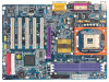
English GA-8PE800(-L) Motherboard Layout KB_MS USB_LAN * C PU_FAN ATX COMA SOC KET478 COMB LPT ATX_12V GA-8PE800 DDR1 DDR2 DDR3 MIC_IN LINE_OUT LINE_IN GAME SUR_CEN -L F_AU DIO AGP_LED RTL8100BL * C D_IN AU X_IN C ODEC P4 Titan IT8 712 SPDIF_IO CI F_U SB1 845P E - Gigabyte GA8PE800 | User Guide - Page 12
.318MHz BIOS ICH4 LPC BUS IT8712 24 M Hz Gam e Port Floppy LPT Port PCICLK (33M Hz) AC97 CODEC 6 USB Ports ATA33/66/100 IDE Channels 33 M Hz PS/2 KB/M ouse COM Ports MIC LINE-IN LINE-OUT PCICLK (33M Hz) USBCLK (48MHz) 14.318 M Hz 33 M Hz "*" For GA-8PE800-L only. GA-8PE800(-L) Motherboard - Gigabyte GA8PE800 | User Guide - Page 13
- 9 - Introduction English - Gigabyte GA8PE800 | User Guide - Page 14
computer, you must complete the following steps: Step 1- Install the Central Processing Unit (CPU) Step 2- Install memory modules Step 3- Install expansion cards Step 4- Connect ribbon cables cable to the power outlet. Continue with the BIOS/software installation. GA-8PE800(-L) Motherboard - 10 - - Gigabyte GA8PE800 | User Guide - Page 15
installing the processor,adhere to the following warning: If you do not match the CPU socket Pin 1 and CPU cut edge well, it will cause improper installation. Please change the insert orientation. Please make sure the CPU type is supported by the motherboard. Step 1-1: CPU Installation Angling - Gigabyte GA8PE800 | User Guide - Page 16
the installation. Please refer to CPUcooling fan user's manual for more detailinstallation procedure. 1. Fasten the heatsink supporting-base onto the CPU socket on the mainboard. 2. Make sure the CPU fan is plugged to the CPU fan connector, than install complete. GA-8PE800(-L) Motherboard - 12 - - Gigabyte GA8PE800 | User Guide - Page 17
in one direction due to the one notches. Wrong orientation will cause improper installation. Please change the insert orientation. The motherboard has 3 dual inline memory module (DIMM) sockets. The BIOS will automatically dete cts me mory type and size. To install the memo ry mod ule, just push it - Gigabyte GA8PE800 | User Guide - Page 18
migration path from existing SDRAM designs due to its availability, pricing and overall market support. PC2100 DDR memory (DDR266) doubles the data rate through reading and writing at a compelling solution for small form factor desktops and notebook applications. GA-8PE800(-L) Motherboard - 14 - - Gigabyte GA8PE800 | User Guide - Page 19
slot bracket of the expansion card. 6. Replace your computer's chassis cover. 7. Power on the computer, if necessary, setup BIOS utility of expansion card from BIOS. 8. Install related driver from the operating system. AGP Card Please carefully pull outthe small white- drawable bar at the end of - Gigabyte GA8PE800 | User Guide - Page 20
supports standard PS/2 keyboard and PS/2 mouse. v USB & LAN * Connector LAN * USB 0 USB 1 "*" For GA-8PE800-L only. GA-8PE800(-L) Motherboard sure your OS supports USB con troller. If your OS d oes n ot sup port USB controller, please contactOS vendor for possible pa tch or driver upgrad e. For - Gigabyte GA8PE800 | User Guide - Page 21
/MIDI Ports Ø This connector supports joystick, MIDIkeyboard and other relate audio devices. Joystick/ MIDI (15 pin Female) y Audio Connectors Line Out (Front Speaker) MIC In (Center and Subwoofer) Line In (Rear Speaker) Ø After install onboard audio driver, you may connectspeaker to Line - Gigabyte GA8PE800 | User Guide - Page 22
9) F_PANEL 10) BAT 2 6 18 4 10 5 17 16 97 11) F_AUDIO 12) SUR_CEN 13) CD_IN 14) AUX_IN 15) SPDIF_IO 16) F_USB1/F_USB2 17) CI 18) CLR_PWD GA-8PE800(-L) Motherboard - 18 - - Gigabyte GA8PE800 | User Guide - Page 23
English 1) ATX_12V (+12VPower Connector) This connector (ATX _12V) suppliesthe CPU operation voltage (Vcore). If this " ATX_ 12V connector" is not connected, system cannotboot. PinNo. Definition 2 1 1 GND 2 GND 4 3 3 +12V 4 +12V 2) ATX (ATX Power) AC power cord - Gigabyte GA8PE800 | User Guide - Page 24
supports Max. current up to 600 mA. PinNo. Definition 1 1 GND 2 +12V 3 Sense 4) SYS_FAN (System FAN Connector) This connector allows you to link with the cooling fan on the system case to lower the system temperature. PinNo. Definition 1 GND 1 2 +12V 3 Sense GA-8PE800(-L) Motherboard - Gigabyte GA8PE800 | User Guide - Page 25
English 5) IDE1/ IDE2(IDE1/IDE2 Connector) Please connect first harddisk to IDE1 and connectCDROM to IDE2. The red stripe of the ribbon cable must be the same side with the Pin1. 39 IDE2 1 40 IDE1 2 6) FDD (Floppy Connector) Please connect the floppy drive ribbon cables to FDD. Itsupports - Gigabyte GA8PE800 | User Guide - Page 26
AGP_LED will light up, indicating a nonsupported graphics card is inserted. Informing users that system might notboot up normally due to AGP 2X (3.3V) is not supported by the chipset. -+ GA-8PE800(-L) Motherboard - 22 - - Gigabyte GA8PE800 | User Guide - Page 27
English 9) F_PANEL (2x10 pins connector) Please connect the power LED, PC peaker, resetswitch and power switch etc of your chassis front panel to the F_PANEL connector according to the pin assignment above. Me ssa g e LED/Po we r / Sleep LED Soft Po wer Connector Speaker Connector MPD MPD + 21 - Gigabyte GA8PE800 | User Guide - Page 28
according to the manufacturer's instructions. If you want to audio connector or of using rear audio connector to play sound. PinNo. Definition 1 MIC 2 GND 10 9 3 REF 4 POWER 21 5 FrontAudio(R) 6 RearAudio(R) 7 Reserved 8 NoPin 9 FrontAudio(L) 10 RearAudio(L) GA-8PE800(-L) Motherboard - Gigabyte GA8PE800 | User Guide - Page 29
SUR_CEN cable. 65 21 Pin No. 1 2 3 4 5 6 Definition SUROUT L SUROUT R GND No Pin CENTER_OUT BASS_OUT 13) CD_IN (CD IN,Black) Connect CD-ROM or DVD-ROM audio out to the connector. PinNo. Definition 1 1 CD-L 2 GND 3 GND 4 CD_R - 25 - Hardware Installation Process - Gigabyte GA8PE800 | User Guide - Page 30
3 GND 4 AUX_R 15) SPDIF_IO (SPDIF In/Out) The SPDIF output is capable of providing digital audio to external speakers or compressed AC3 data to an external Dolby Digital Decoder. Use this feature only when . 1 2 3 4 5 6 Definition VCC No Pin SPDIF SPDIFI GND GND GA-8PE800(-L) Motherboard - 26 - - Gigabyte GA8PE800 | User Guide - Page 31
Dy+ GND GND No Pin NC 17) CI (CASE OPEN) This 2 pin connector allows your system to enable or disable the "case open" item in BIOS if the system case begin remove. PinNo. Definition 1 1 Signal 2 GND - 27 - Hardware Installation Process - Gigabyte GA8PE800 | User Guide - Page 32
English 17) CLR_PWD When Jum per is set to "open" and system is restarted, the password that is set will be cleared. On the contrary when Jumper is set to "close", the current status remains. 1 open: Clear password 1 close: Normal GA-8PE800(-L) Motherboard - 28 - - Gigabyte GA8PE800 | User Guide - Page 33
- 29 - Hardware Installation Process English - Gigabyte GA8PE800 | User Guide - Page 34
English GA-8PE800(-L) Motherboard - 30 - - Gigabyte GA8PE800 | User Guide - Page 35
ed Restore the previous CMOS value from CMOS, only for Option Page Setup Menu Load the file-safe default CMOS value from BIOS default table Load the Optimized Defaults Q-Flash function System Information Save all the CMOS changes, only for Main Menu - 31 - Gigabyte GA8PE800 | User Guide - Page 36
want, p lease press "Ctrl+F1" to search th e advanced optio n widden. l Standard CMOS Features This setup page includes all the items in standard compatible BIOS. l Advanced BIOS Features This setup page includes all the items of Award special enhanced features. GA-8PE800(-L) Motherboard - 32 - - Gigabyte GA8PE800 | User Guide - Page 37
the System auto detect Temperature, voltage, fan, speed. l Frequency/Voltage Control This setup page is control CPU's clock and frequency ratio. l Top Performance If you wish to maximize the performance of your system, Without Saving Abandon all CMOS value changes and exit setup. - 33 - BIOS Setup - Gigabyte GA8PE800 | User Guide - Page 38
Sat. Driv e A Driv e B Floppy 3 Mode Support Halt On Base Memory Ex tended Memory Total Memory 1.44M, BIOS and is display only 8Month 8Day 8Year The month, Jan. Through Dec. The day , from 1 to 31 (or the max imum allow ed in the month) The y ear, from 1999 through 2098 GA-8PE800(-L) Motherboard - Gigabyte GA8PE800 | User Guide - Page 39
to F that has been installed in the computer. There are two types: auto type, and manual type. Manual type is user-definable; Auto type which will automatically detect HDD type. Note that the specifications . 82.88M, 3.5 in. 3.5 inch double-sided driv e; 2.88M by te capacity . - 35 - BIOS Setup - Gigabyte GA8PE800 | User Guide - Page 40
Mode Support ( motherboard, or 640 K for systems with 640 K or more memory installed on the motherboard. Extended Memory The BIOS determines how much extended memory is present during the POST. This is the amount of memory located above 1 MB in the CPU's memory address map. GA-8PE800(-L) Motherboard - Gigabyte GA8PE800 | User Guide - Page 41
Adv anced BIOS Features First Boot Dev ice [Floppy ] Item Help Second Boot Dev ice Third Boot Dev ice Boot Up Floppy Seek Passw ord Check # CPU Hy 3: Adv anced BIOS Features " # " System will detect automatically and show up when you install the Intel® Pentium® 4 processor with HT Technology. - Gigabyte GA8PE800 | User Guide - Page 42
Boot Up Fl oppy Seek During POST, BIOS will determine the floppy disk processors mode supported. (Default v alue) 8Disabled Disables CPU Hy per Threading. CInit Display First 8AGP Set Init Display First to AGP. (Default v alue) 8PCI Set Init Display First to PCI. GA-8PE800(-L) Motherboard - Gigabyte GA8PE800 | User Guide - Page 43
hard disk IDE2 Conductor Cable [Auto] controller card is USB Controller USB Key board Support USB Mouse Support AC97 Audio Onboard H/W LAN * Onboard LAN Boot ROM * Onboard Serial Port 1 Onboard alue) 8Disabled Disable onboard 2nd channel IDE port. "*" For GA-8PE800-L only. - 39 - BIOS Setup - Gigabyte GA8PE800 | User Guide - Page 44
detected by BIOS. ( Support. (Default v alue) C USB Mouse Support 8Enabled Enable USB Mouse Support. 8Disabled Disable USB Mouse Support. (Default v alue) C AC97 Audio 8Auto Enable onboard AC'97 audio function. (Default Value) 8Disabled Disable this function. GA-8PE800(-L) Motherboard - Gigabyte GA8PE800 | User Guide - Page 45
1 and address is 2E8. 8Disabled Disable onboard Serial port 1. C Onboard Serial Port 2 8Auto BIOS w ill automatically setup the port 2 address. 83F8/IRQ4 Enable onboard Serial port 2 and address is Enable onboard LPT port and address is 3BC/IRQ7. "*" For GA-8PE800-L only. - 41 - BIOS Setup - Gigabyte GA8PE800 | User Guide - Page 46
330.(Default Value) 8Disabled Disable this function. CMidi Port IRQ 85 Set Midi Port IRQ to 5. 810 Set Midi Port IRQ to 10. (Default Value) GA-8PE800(-L) Motherboard - 42 - - Gigabyte GA8PE800 | User Guide - Page 47
off instantly . (Default v alue) 8Delay 4 Sec. Press pow er button 4 sec to Pow er off. Enter suspend if button is pressed less than 4 sec. - 43 - BIOS Setup - Gigabyte GA8PE800 | User Guide - Page 48
. 8Soft-Off Alw ay s in Off state w hen AC back. (Default v alue) 8Full-On Alw ay s pow er on the sy stem w hen AC back. GA-8PE800(-L) Motherboard - 44 - - Gigabyte GA8PE800 | User Guide - Page 49
Assignment 8Auto Auto assign IRQ to PCI 3. (Default v alue) 83,4,5,7,9,10,11,12,14,15 Set IRQ 3,4,5,7,9,10,11,12,14,15 to PCI 3. - 45 - BIOS Setup - Gigabyte GA8PE800 | User Guide - Page 50
Status" to "Enabled" and sav e CMOS, y our computer w ill res tart. C Current Voltage (V) VCORE / +1.5V / +3.3V / +5V / +12V 8Detect sy stem's v oltage status automatically . C Current CPU Temperature 8Detect CPU Temp. automatically. GA-8PE800(-L) Motherboard - 46 - - Gigabyte GA8PE800 | User Guide - Page 51
this function.(Default v alue) C CPU FAN Fail Warning 8Disabled Fan Warning Function Disable. (Default v alue) 8Enabled Fan Warning Function Enable. C SYSTEM FAN Fail Warning 8Disabled Fan Warning Function Disable. (Default v alue) 8Enabled Fan Warning Function Enable. - 47 - BIOS Setup - Gigabyte GA8PE800 | User Guide - Page 52
up before enter CMOSsetup utility , wait for 20 sec for times out reboot . When time out occur, sy stem w ill reset and run at CPU default Host clock at nex t boot. 8Disable Disable CPU Host Clock Control.(Default v alue) 8Enable Enable CPU Host Clock Control. GA-8PE800(-L) Motherboard - 48 - - Gigabyte GA8PE800 | User Guide - Page 53
8You can choose those mode to adjust PCI/ AGP frequency. (Select PCI/AGP frequency asy nchronous w ith CPU frequency ). CHost/DRAM Clock Ratio for FSB(Front Side Bus) frequency =400MHz, 82.0 Memory Frequency = Control to +0.1V. 8+0.2V Set DIMM Ov erVoltage Control to +0.2V. - 49 - BIOS Setup - Gigabyte GA8PE800 | User Guide - Page 54
2V Set AGP Ov erVoltage Control to +0.2V. 8+0.3V Set AGP Ov erVoltage Control to +0.3V. C CPU Voltag e Control 8 Supports adjustable CPU Vcore from 0.8375V to 1.6V by 0.0125V step. (Default v alue: Normal) C Normal CPU Vcore 8 Display y our CPU Vcore Voltage. GA-8PE800(-L) Motherboard - 50 - - Gigabyte GA8PE800 | User Guide - Page 55
Softw are }Standard CMOS Features Top Performance }Adv anced BIOS Features Load Fail-Safe Defaults }Integrated PeripThoepralPserformance Load Optimized stem is not perform enough, the reliability or stability problem w il appear sometimes, and w e w ill recommend y ou disabling the option to av oid - Gigabyte GA8PE800 | User Guide - Page 56
(C) 1984-2003 Aw ard Softw are }Standard CMOS Features Top Performance }Adv anced BIOS Features Load Fail-Safe Defaults }Integrated Peripherals Load Optimized Defaults }Pow er Management SLeotuapd the system parameters that allow minimum system performance. GA-8PE800(-L) Motherboard - 52 - - Gigabyte GA8PE800 | User Guide - Page 57
Load Optimized Defaults CMOS Setup Utility -Copy right (C) 1984-2003 Aw ard Softw are }Standard CMOS Features Top Performance }Adv anced BIOS Features Load Fail-Safe Defaults }Integrated Peripherals Load Optimized Defaults }Pow er Management Setup Set Superv isor Passw ord }PnP/PCI - Gigabyte GA8PE800 | User Guide - Page 58
A dvance BIOS Features Menu, you will be prompted for the password every time the system is rebooted or any time you try to enter Setup Menu. If youselect "Setup" at "Password Check" inAdvance BIOS Features Menu, you will be prompted only when you try to enter Setup. GA-8PE800(-L) Motherboard - 54 - Gigabyte GA8PE800 | User Guide - Page 59
English Save & Exit Setup CMOS Setup Utility -Copy right (C) 1984-2003 Aw ard Softw are }Standard CMOS Features Top Performance }Adv anced BIOS Features Load Fail-Safe Defaults }Integrated Peripherals Load Optimized Defaults }Pow er Management Setup Set Superv isor Passw ord }PnP/PCI - Gigabyte GA8PE800 | User Guide - Page 60
right (C) 1984-2003 Aw ard Softw are }Standard CMOS Features Top Performance }Adv anced BIOS Features Load Fail-Safe Defaults }Integrated Peripherals Load Optimized Defaults }Pow er Management Setup saving to RTC CMOS. Type "N"will return to Setup Utility. GA-8PE800(-L) Motherboard - 56 - - Gigabyte GA8PE800 | User Guide - Page 61
- 57 - BIOS Setup English - Gigabyte GA8PE800 | User Guide - Page 62
English GA-8PE800(-L) Motherboard - 58 - - Gigabyte GA8PE800 | User Guide - Page 63
to update it. Maybe not like others, you are very experienced in BIOS updating and spend quite a lot oftime to do it. Butof course you It's free! Now, ifyou buy a Gigabyte's motherboard, you could find this amazing software in the attached driver CD. But please remember,connected to internetat - Gigabyte GA8PE800 | User Guide - Page 64
byEasyTune 4. Please find the products supported list in the web site. *Any "Overclocking action" is at u ser's risk, Gig abyte Technolo gy will not be responsible for any damage or instability to your processor, motherboard, or any other components. GA-8PE800(-L) Motherboard - 60 - - Gigabyte GA8PE800 | User Guide - Page 65
, no more fooling around anyOS. B. How to use Q-Flash? a. After power on the computer, pressing immediately during POST (Power On Self Test) it will allow you to enter AWARD BIOS CMOS SETUP, then press to enter Q-Flash utility. CMOS Setup Utility-Copyright (C) 1984-2003 Award Software - Gigabyte GA8PE800 | User Guide - Page 66
the BIOS file. !Press Enter to Run. Are you sure to update BIOS? [Enter] to contiune Or [ESC] ot abort... !Press Enter to Run. !! COPY BIOS Completed -Pass !! Please press any keyto continue Congratulation!You have completed the flashed and now can restartsystem. GA-8PE800(-L) Motherboard - 62 - Gigabyte GA8PE800 | User Guide - Page 67
English Method 2: BIOS Flash Utility BIOS Flash Procedure We use GA-7VTXmotherboard and Flash841 BIOS flash utility as example. Please flash the BIOS according to the following procedures ifyou are now under the DOS mode. Flash BIOSProcedure: STEP 1: (1) Please make sure your system has installed - Gigabyte GA8PE800 | User Guide - Page 68
: This procedure will erase all the prior data on that floppy, so please proceed accordingly. (3) After the floppy has been formatted completely, please press "Close". GA-8PE800(-L) Motherboard - 64 - - Gigabyte GA8PE800 | User Guide - Page 69
English STEP 3: Download BIOS and BIOS utility program. (1) Please go to Gigabyte website http://www.gigabyte.com.tw/index.html, and click "Support". (2) From Supportzone, click the "Motherboards BIOS & Drivers". - 65 - Technical Reference - Gigabyte GA8PE800 | User Guide - Page 70
-7VTX by Modelor Chipsetoptional menu to obtain BIOS flash files. (4) Selectan appropriate BIOS version (Forexample: F4), and click to download the file. Itwill pop up a file download screen, then selectthe "Open this file from its currentlocation" and press "OK". GA-8PE800(-L) Motherboard - 66 - - Gigabyte GA8PE800 | User Guide - Page 71
English (5) Atthis time the screen shows the following picture, please click "Extract" button to unzip the files. (6) Please extractthe download files into the clean bootable floppy disk A mentioned in STEP 2, and press "Extract". - 67 - Technical Reference - Gigabyte GA8PE800 | User Guide - Page 72
AUTO DETECTION LOAD BIOS DEFAULTS SAVE & EXIT SETUP LOAD SETUP DEFAULTS EXIT WITHOUT SAVING ESC: Quit hifg : Select Item (Shift)F2 : Change Color F5: Old Values F6: Load BIOS Defaults F7: Load Setup Defaults F10:Save & Exit Tim e, Date , Hard Disk Type... GA-8PE800(-L) Motherboard - 68 - - Gigabyte GA8PE800 | User Guide - Page 73
the arrows to highlightthe item "1st Boot Device", and then use the "Page Up" or "Page Down" keys to select "Floppy". AMIBIOS SETUP - BIOS FEATURES SETUP ( C ) 2001 American Megatrends, Inc. All Rights Reserved 1st Boot Device 2nd Boot Device 3rd Boot Device S.M .A.R.T. for Hard Disks BootUp Num - Gigabyte GA8PE800 | User Guide - Page 74
dir/w" and press "Enter" to check the entire files in floppy A. Then type the "BIOS flash utility" and "BIOS file" after A:\>. In this case you have to type "A:\> Flash841 7VTX.F4" and then -upper screen. Rightafter that,press "Enter" to startBIOS Flash Utility. GA-8PE800(-L) Motherboard - 70 - - Gigabyte GA8PE800 | User Guide - Page 75
Beware: Please do not turn off the system while you are upgrading BIOS. It will render your BIOS corrupted and system totally inoperative. Are you sure to flash the BIOS? [Enter] to continue Or [Esc] to cancel? (4) The BIOS flash completed. Please press [ESC] to exit Flash Utility. EXIT? [Enter] to - Gigabyte GA8PE800 | User Guide - Page 76
DE(YH/DND)?ANUTO DETECTION LOAD BIOS DEFAULTS SAVE & EXIT SETUP LOAD SETUP DEFAULTS EXIT WITHOUT SAVING ESC: Quit hifg : Select Item (Shift)F2 : Change Color F5: Old Values F6: Load BIOS Defaults F7: Load Setup Defaults F10:Save & Exit Load Setup Defaults GA-8PE800(-L) Motherboard - 72 - - Gigabyte GA8PE800 | User Guide - Page 77
". System will ask "SAVE to CMOS and EXIT (Y/N)?" Press "Y" and "Enter" keys to confirm. Now the system will rebootautomatically, the new BIOS setting willbe taken effectnextboot-up. AMIBIOS SIM PLE SETUP UTILITY - VERSION 1.24b (C) 2001 American Megatrends, Inc. All Rights Reserved STANDARD CMOS - Gigabyte GA8PE800 | User Guide - Page 78
"OK". (3) (4) Methods and steps: I. Update BIOS through Internet a. Click "Internet Update" icon b. Click "Update New BIOS" icon c. Select @BIOSTM sever d. Selectthe exactmodelname on your motherboard e. System will automatically download and update the BIOS. GA-8PE800(-L) Motherboard - 74 - - Gigabyte GA8PE800 | User Guide - Page 79
8PE800.F1). e. Complete update processfollowing the instruction. III. Save BIOS In the very beginning, there is "Save Current BIOS" icon shown in dialog box.It means to save the current BIOS version. IV. Check outsupported motherboard supported. Note: a. In method I,ifitshows two or more motherboard - Gigabyte GA8PE800 | User Guide - Page 80
installation of the audio driver, you'll find an icon on the taskbar's status area. Click the audio icon "Sound Effect" from the windows tray at the bottom of the screen. STEP 3: Select "Speaker Configuration", and choose the "2 channels for stereo speakers out put". GA-8PE800(-L) Motherboard - 76 - Gigabyte GA8PE800 | User Guide - Page 81
Connect the front channels to "Line Out", the rear channels to "Line In". STEP 2 : After installation of the audio driver, you 'll find an icon on the taskbar's status area. Click the audio icon "Sound Effect" from the windows tray at the bottom of the screen. STEP 3 : Select "Speaker Configuration - Gigabyte GA8PE800 | User Guide - Page 82
's status area. Click the audio icon "Sound Effect" from the windows tray at the bottom of the screen. STEP 3 : Select "Speaker Configuration", and choose the "6 channels for 5.1 speakers out put". Disable "Only SURROUND-KIT" and pess "OK". Line Out Line In MIC In GA-8PE800(-L) Motherboard - 78 - - Gigabyte GA8PE800 | User Guide - Page 83
channels. It is the best solution if you need 6 channel output, Line In and MIC at the same time. "SURROUND-KIT" is included in the GIGABYTE unique "Audio Com bo Kit" as picture. STEP 1 : Insert the "SURROUND-KIT" in the back of the case ,and fix it with the screw. STEP 2 : Connect - Gigabyte GA8PE800 | User Guide - Page 84
's SUB CENTER. STEP 4 : Click the audio icon "Sound Effect" from the windows tray at Audio Output ModeNotes: When the "Environment settings" is "None", the sound would be perform ed as stereo m ode(2 channels output). Please select the other settings for 6 channels output. GA-8PE800(-L) Motherboard - Gigabyte GA8PE800 | User Guide - Page 85
English SPDIF Output Device (Optional Device) A "SPDIF output" device is available on the motherboard. Cable with rear bracket is provided and could link to the "SPDIF output" connector (As picture.) For the further linkage to decoder, rear bracketprovides coaxialcable - Gigabyte GA8PE800 | User Guide - Page 86
English GA-8PE800(-L) Motherboard - 82 - - Gigabyte GA8PE800 | User Guide - Page 87
22) Insert the driver CD-title that came with your motherboard into your CD-ROM drive, the driver CD-title will auto start and show the installation guide. If not, to install the driver manually or switch to the to install the drivers automatically. Massage: Some device drivers will restart your - Gigabyte GA8PE800 | User Guide - Page 88
/ICH2/ICH4 AC97 audio. n USB Driver Patch This patch driver can help you to resolve some USB device issue on XP. n Intel/NEC USB 2.0 Driver It is recommended that you use the Microsoft Windows update for the most updated driver for XP/2K. "*" For GA-8PE800-L only. GA-8PE800(-L) Motherboard - 84 - - Gigabyte GA8PE800 | User Guide - Page 89
based utility which is used to browse the DMI/SMBIOS information of the system. n Face-Wizard New utility for adding BIOS logo. n @BIOS Gigabyte windows flash BIOS utility. n Acrobat e-Book Useful utility from Adobe. n Acrobat Reader Popular utility from Adobe for reading .PDF file format documents - Gigabyte GA8PE800 | User Guide - Page 90
English SOFTWARE INFORMATION This page list the contects of softwares and drivers in this CD title. HARDWARE INFORMATION This page lists all device you have for this motherboard. CONTACT US Please see the last page for details. GA-8PE800(-L) Motherboard - 86 - - Gigabyte GA8PE800 | User Guide - Page 91
Acronyms Acronyms ACPI APM AGP AMR ACR BIOS CPU CMOS CRIMM CNR DMA DMI DIMM DRM DRAM DDR ECP ESCD ECC EMC EPP ESD FDD FSB HDD IDE IRQ Meaning Advanced Configuration and Power Interface Advanced Power Management Accelerated Graphics Port Audio Modem Riser Advanced Communications Riser Basic Input - Gigabyte GA8PE800 | User Guide - Page 92
ISA LAN I/O LBA LED MHz MIDI MTH MPT NIC OS OEM PAC POST PCI RIMM SCI SECC SRAM Meaning Input Output Advanced Programmable Input Controller Rambus in-line Memory Module Special Circumstance Instructions Single Edge Contact Cartridge Static Random Access Memory GA-8PE800(-L) Motherboard - 88 - - Gigabyte GA8PE800 | User Guide - Page 93
Lot Number: BIOS version: O.S./A.S.: Hardware Mfs. Model name Size: Configuration CPU Memory Brand Video Card Audio Card HDD CD-ROM / DVD-ROM Modem Network AMR / CNR Keyboard Mouse Power supply Other Device Phone No.: PCB revision: Driver/Utility: Problem Description: & - 89 - Gigabyte GA8PE800 | User Guide - Page 94
in the CPU fan connector. Plug in the AC power connector. Failure has been excluded. No Insert and push the memory module vertically into the DIMM slot. Failure has been excluded. Insert the VGA card. Then plug in ATX power cable and turn on the system. A GA-8PE800(-L) Motherboard - 90 - Gigabyte GA8PE800 | User Guide - Page 95
If the above procedure unable to solve your problem, please contact with your local retailer or national distributor for help. Or, you could submit your question to the service mail via Gigabyte website technical support zone (http://www.gigabyte.com.tw). The appropriate response will be provided - Gigabyte GA8PE800 | User Guide - Page 96
Address: www.gigabyte.com.cn Beijing Office Tel:86-10-82856054 86-10-82856064 86-10-82856094 Fax: 86-10-82856575 Web Address: www.gigabyte.com.cn E-mail:[email protected] Chengdu Office Tel: 86-28-85236930 Fax: 86-28-85256822 Web Address: www.gigabyte.com.cn GA-8PE800(-L) Motherboard - 92
-
 1
1 -
 2
2 -
 3
3 -
 4
4 -
 5
5 -
 6
6 -
 7
7 -
8
-
9
-
10
-
11
-
12
-
13
-
14
-
15
-
16
-
17
-
18
-
19
-
20
-
21
-
22
-
23
-
24
-
25
-
26
-
27
-
28
-
29
-
30
-
31
-
32
-
33
-
34
-
35
-
36
-
37
-
38
-
39
-
40
-
41
-
42
-
43
-
44
-
45
-
46
-
47
-
48
-
49
-
50
-
51
-
52
-
53
-
54
-
55
-
56
-
57
-
58
-
59
-
60
-
61
-
62
-
63
-
64
-
65
-
66
-
67
-
68
-
69
-
70
-
71
-
72
-
73
-
74
-
75
-
76
-
77
-
78
-
79
-
80
-
81
-
82
-
83
-
84
-
85
-
86
-
87
-
88
-
89
-
90
-
91
-
92
-
93
-
94
-
95
-
96
 |
 |
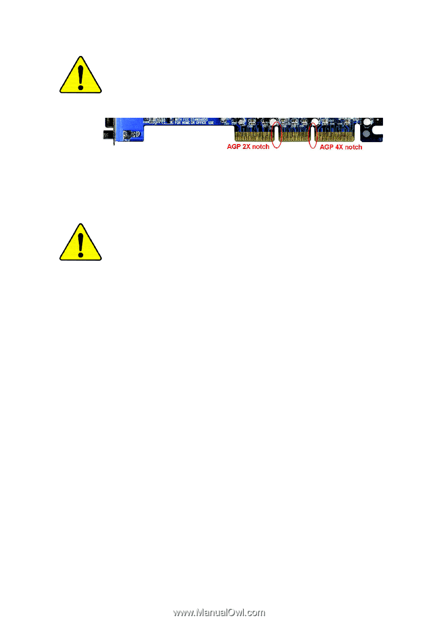
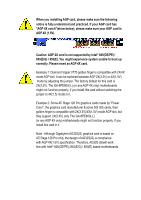
When you installing AGP card, please make sure the following
notice is fully understood and practiced. If your AGP card has
"AGP 4X notch"(show below), please make sure your AGP card is
AGP 4X (1.5V).
Caution: AGP 2X card is not supported by Intel
®
845(GE/PE) /
845(E/G) / 850(E). You might experience system unable to boot up
normally. Please insert an AGP 4X card.
Example 1: Diamond Vipper V770 golden finger is compatible with 2X/4X
mode AGP slot. It can be switched between AGP 2X(3.3V) or 4X(1.5V)
mode by adjusting the jumper. The factory default for this card is
2X(3.3V). The GA-8PE800(-L) (or any AGP 4X only) motherboards
might not function properly, if you install this card without switching the
jumper to 4X(1.5) mode in it.
Example 2: Some ATi Rage 128 Pro graphics cards made by "Power
Color", the graphics card manufacturer & some SiS 305 cards, their
golden finger is compatible with 2X(3.3V)/4X(1.5V) mode AGP slot, but
they support 2X(3.3V) only. The GA-8PE800(-L)
(or any AGP 4X only) motherboards might not function properly, If you
install this card in it.
Note : Although Gigabyte's AG32S(G) graphics card is based on
ATi Rage 128 Pro chip, the design of AG32S(G) is compliance
with AGP 4X(1.5V) specification. Therefore, AG32S (G)will work
fine with Intel
®
845(GE/PE) /845(E/G) / 850(E) based motherboards.