Gigabyte GA8PE800 User Guide - Page 6
English - bios
 |
View all Gigabyte GA8PE800 manuals
Add to My Manuals
Save this manual to your list of manuals |
Page 6 highlights
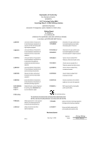
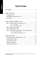
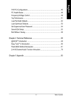
English Table of Content Item Checklist 4 Chapter 1 Introduction 5 Features Summary 5 GA-8PE800(-L) Motherboard Layout 7 Block Diagram 8 Chapter 2 Hardware Installation Process 10 Step 1: Install the Central Processing Unit (CPU 11 Step 1-1: CPU Installation 11 Step 1-2 : CPU Cooling Fan Installation 12 Step 2: Install memory modules 13 Step 3: Install expansion cards 15 Step 4: Connect ribbon cables, cabinet wires, and power supply 16 Step 4-1: I/O Back Panel Introduction 16 Step 4-2: Connectors & Jumper Setting Introduction 18 Chapter 3 BIOS Setup 31 The Main Menu (For example: BIOS Ver. : F7a 32 Standard CMOS Features 34 Advanced BIOS Features 37 Integrated Peripherals 39 Power Management Setup 43 GA-8PE800(-L) Motherboard - 2 -
-
 1
1 -
 2
2 -
 3
3 -
 4
4 -
 5
5 -
 6
6 -
 7
7 -
 8
8 -
 9
9 -
 10
10 -
 11
11 -
 12
12 -
13
-
14
-
15
-
16
-
17
-
18
-
19
-
20
-
21
-
22
-
23
-
24
-
25
-
26
-
27
-
28
-
29
-
30
-
31
-
32
-
33
-
34
-
35
-
36
-
37
-
38
-
39
-
40
-
41
-
42
-
43
-
44
-
45
-
46
-
47
-
48
-
49
-
50
-
51
-
52
-
53
-
54
-
55
-
56
-
57
-
58
-
59
-
60
-
61
-
62
-
63
-
64
-
65
-
66
-
67
-
68
-
69
-
70
-
71
-
72
-
73
-
74
-
75
-
76
-
77
-
78
-
79
-
80
-
81
-
82
-
83
-
84
-
85
-
86
-
87
-
88
-
89
-
90
-
91
-
92
-
93
-
94
-
95
-
96
 |
 |

- 2 -
GA-8PE800(-L) Motherboard
English
T
a
b
l
e
o
f
C
o
n
t
e
n
t
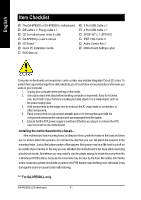
Item Checklist
......................................................................................
4
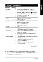
Chapter 1 Introduction
.........................................................................
5
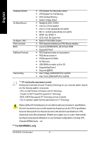
Features Summary
..........................................................................................
5
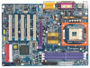
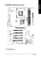
GA-8PE800(-L) Motherboard Layout
..............................................................
7
Block Diagram
..................................................................................................
8
Chapter 2 Hardware Installation Process
............................................
10
Step 1: Install the Central Processing Unit (CPU)
........................................
11
Step 1-1: CPU Installation
...........................................................................................
11
Step 1-2 : CPU Cooling Fan Installation
......................................................................
12
Step 2: Install memory modules
...................................................................
13
Step 3: Install expansion cards
.....................................................................
15
Step 4: Connect ribbon cables, cabinet wires, and power supply
..............
16
Step 4-1: I/O Back Panel Introduction
..........................................................................
16
Step 4-2: Connectors & Jumper Setting Introduction
....................................................
18
Chapter 3 BIOS Setup
.......................................................................
31
The M ain Menu (For example: BIOS Ver. : F7a)
.........................................
32
Standard CMOS Features
.............................................................................
34
Advanced BIOS Features
..............................................................................
37
Integrated Peripherals
..................................................................................
39
Power Management Setup
............................................................................
43