Gigabyte GA8PE800 User Guide - Page 27
F_PANEL 2x10 pins connector
 |
View all Gigabyte GA8PE800 manuals
Add to My Manuals
Save this manual to your list of manuals |
Page 27 highlights
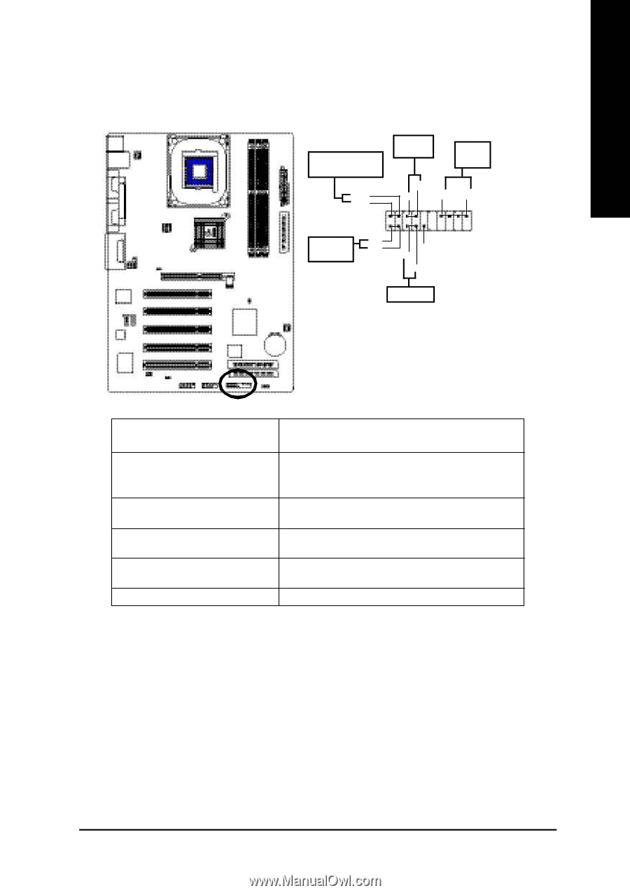
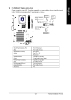
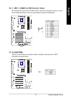
English 9) F_PANEL (2x10 pins connector) Please connect the power LED, PC peaker, resetswitch and power switch etc of your chassis front panel to the F_PANEL connector according to the pin assignment above. Me ssa g e LED/Po we r / Sleep LED Soft Po wer Connector Speaker Connector MPD MPD + 21 11 ID E H ard Di sk HD + HD- Active L ED PW - PW + SPK+ 1 1 1 NC RSE- R SE+ SPK- 20 19 Reset Swi tch HD (IDEHard DiskActive LED) (Blue) SPK(Speaker Connector) (Amber) RES (Reset Switch) (Green) PW(Soft Power Connector) (Red) M SG(M essage LED/Power/ Sleep LED)(Yellow) NC( Purple) Pin 1: LED anode(+) Pin2: LEDcathode(-) Pin 1: VCC(+) Pin 2- Pin 3: NC Pin 4: Data(-) Open:Normal Operation Close: Reset Hardware System Open:Normal Operation Close:Power On/Off Pin 1: LED anode(+) Pin2: LEDcathode(-) NC - 23 - Hardware Installation Process
-
 1
1 -
2
-
3
-
4
-
5
-
6
-
7
-
8
-
9
-
10
-
11
-
12
-
13
-
14
-
15
-
16
-
17
-
18
-
19
-
20
-
21
-
 22
22 -
 23
23 -
 24
24 -
 25
25 -
 26
26 -
 27
27 -
 28
28 -
 29
29 -
 30
30 -
 31
31 -
 32
32 -
33
-
34
-
35
-
36
-
37
-
38
-
39
-
40
-
41
-
42
-
43
-
44
-
45
-
46
-
47
-
48
-
49
-
50
-
51
-
52
-
53
-
54
-
55
-
56
-
57
-
58
-
59
-
60
-
61
-
62
-
63
-
64
-
65
-
66
-
67
-
68
-
69
-
70
-
71
-
72
-
73
-
74
-
75
-
76
-
77
-
78
-
79
-
80
-
81
-
82
-
83
-
84
-
85
-
86
-
87
-
88
-
89
-
90
-
91
-
92
-
93
-
94
-
95
-
96
 |
 |